08 external cable connection – Tweco GC-3000 Gas Control User Manual
Page 20
INSTALLATION PROCEDURES
16
Manual 0-2477
A-01163
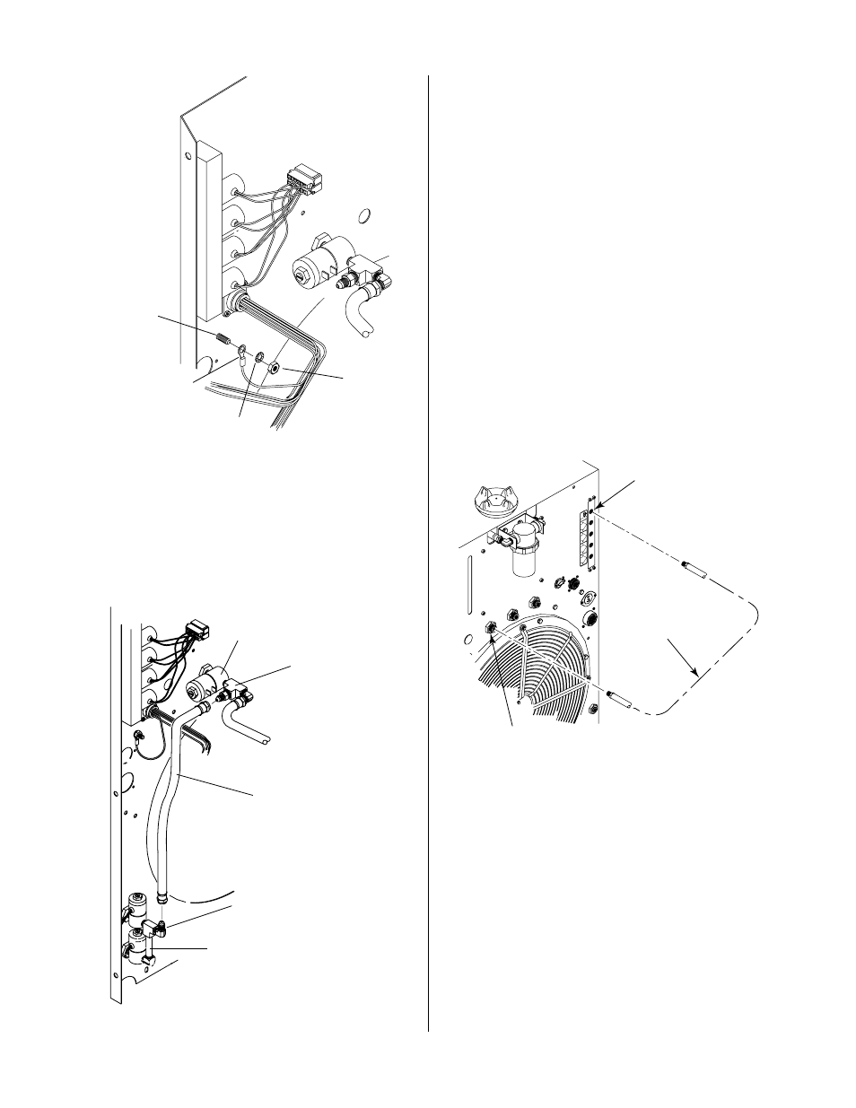
Ground
Stud
Star Washer
Nut
Output Wiring
Harness Ground
Figure 3-13 Ground Wire Connection
D. Hose Assemblies
1. Locate the Secondary Gas Hose Assembly in the Gas
Control components.
2. Connect one end of the Hose Assembly to the elbow
fitting on the Nitrogen/Other Secondary Gas Assem-
bly.
Secondary Gas
Solenoid
A-01165
Secondary Gas
T-Fitting
Secondary Gas
Hose
Nitrogen/Other Secondary
Gas Assembly
Elbow Fitting
Figure 3-14 Secondary Hose Assembly Installation
3. Locate the Secondary Gas Solenoid on the inside of
the Power Supply Rear Panel.
4. Remove the cover installed over the end of the T-fit-
ting.
5. Connect the othe end of the Hose Assembly to the T-
fitting.
6. Reinstall the Power Supply Left Side Panel.
This completes the installation of the components inside
the Merlin 3000 Power Supply.
E. Plasma Gas Hose Connection (External)
1. Locate the Plasma Gas Hose Assembly in the Gas Con-
trol components.
2. Apply thread sealant to the NPT fitting on the end of
the Hose Assembly.
3. Connect the NPT fitting to the PLASMA GAS fitting
on the Power Supply Rear Panel.
OUTPUT
OUTPUT
TO
TO
CONTROL
CONTROL
MODULE
MODULE
AIR
PLASMA
PLASMA
INPUT
INPUT
N2
PLASMA
PLASMA
INPUT
INPUT
O2
PLASMA
PLASMA
INPUT
INPUT
PLASMA GAS
PLASMA GAS
Ar/H
2
PLASMA
PLASMA
INPUT
INPUT
PLASMA GAS
Input Fitting
Plasma Gas Manifold
OUTPUT Fitting
A-01158
Plasma Gas
Hose Assembly
Figure 3-15 Plasma Hose Assembly Installation
4. Connect the Inert-B fitting of the Hose Assembly to
the Plasma Gas Manifold OUTPUT connection at the
rear of the Power Supply.
3.08 External Cable Connection
The Gas Control has only one output connector on the
rear panel. The Gas Control Interface Cable is connected
to this output. The other end of the cable is connected to
the Power Supply.