Tweco GC-3000 Gas Control User Manual
Page 19
Manual 0-2477
15
INSTALLATION PROCEDURES
5. Secure the assembly to the Rear Panel with the two
nuts provided.
C. Wiring Harness Assembly
1. Locate the Wiring Harness Assembly included with
the Gas Control components.
2. Locate the snap in plug in the Output Connector cut-
out on the Power Supply Rear Panel.
Power Supply
Rear Panel
Output Connector
Snap In Plug
A-01161
Figure 3-10 Output Connector Cutout Plug
3. Place the output connector (J63) on the Wiring Har-
ness Assembly into the cutout.
4. Secure the output connector to the Rear Panel with the
two screws and nuts provided.
A-01162
Mounting
Screws
Output
Connector
Mounting
Nuts
Figure 3-11 Output Connector Installation
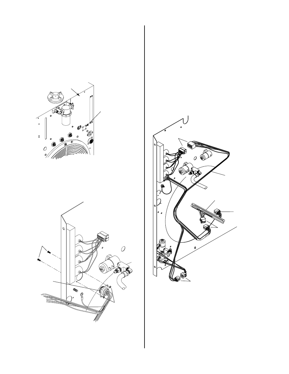
5. On the existing wire harness in the Power Supply dis-
connect the connector at J51.
6. Connect the three connectors on the Gas Control Wir-
ing Harness Assembly as follows (refer to the follow-
ing figure for details):
• One connector, 12 circuit, to the Plasma Gas Mani-
fold Assembly (J60)
• One connector, 6 circuit, to the Nitrogen/Other Sec-
ondary Gas Assembly (J61)
• One connector, 8 circuit, to the existing wiring har-
ness connector (J51)
J61
J51
J60
A-01164
Old J51
(No Connection)
Existing Wire Harness
Gas Control
Wire Harness
Figure 3-12 Gas Control Wiring Harness Assembly
Installation
7. Connect the green/yellow ground wire to the ground
stud on the Rear Panel with the nut and washer pro-
vided.