06 gas control assembly installation – Tweco GC-3000 Gas Control User Manual
Page 16
INSTALLATION PROCEDURES
12
Manual 0-2477
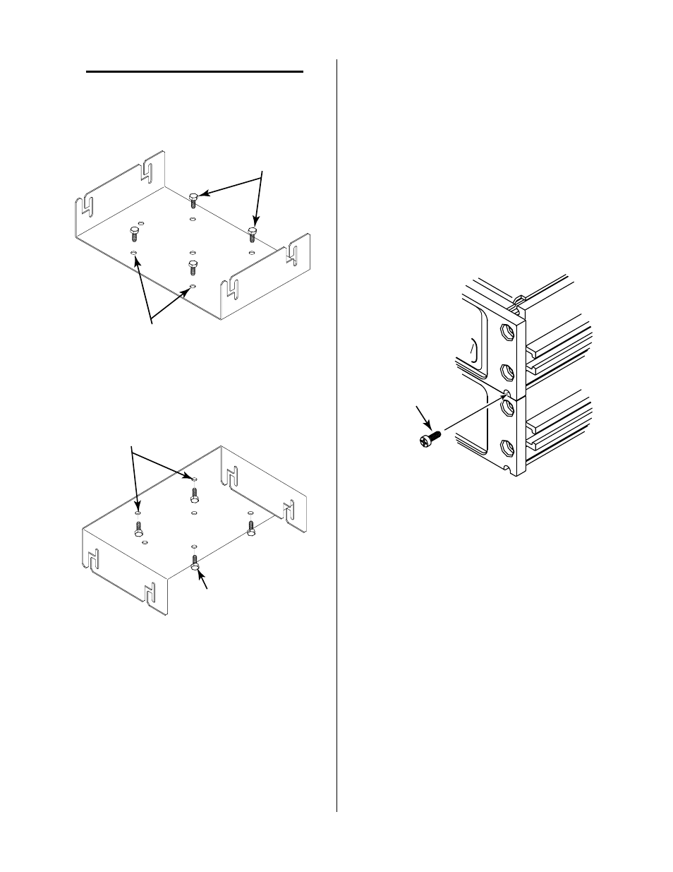
NOTE
There are seven holes provided in the Mounting
Bracket. Use any four holes that are convenient
for the application.
1/4" Mounting Bolts
(Not Supplied)
Mounting Holes
(Seven Places)
A-00671
Figure 3-1 Bracket Mounting On Top Of Surface
A-00672
1/4" Mounting Bolts
(Not Supplied)
Mounting Holes
(Seven Places)
Figure 3-2 Bracket Mounting Underneath Surface
3.06 Gas Control Assembly
Installation
The Gas Control can be installed separately, or together
with the Remote Control and Standoff Control Accesso-
ries. The enclosures for all units are designed to be placed
one on top of the other and secured together with four
#6-32x1/2 inch thread forming screws, two in front panel
and two in rear panel. It makes no difference which unit
goes on top as the installation is the same.
Install the Gas Control Assembly per the following pro-
cedure:
1. Install the Mounting Bracket per Section 3.05.
2. If the Gas Control is to be installed together with
the Remote and Standoff Controls do the follow-
ing:
a. Decide which unit will be the top unit, the Gas
Control, Remote Control, or Standoff Control.
b. Secure the two units together with four #6-
32x1/2 inch thread forming screws (supplied)
inserted at the front and rear panels (two
screws each) in the holes provided.
#6-32 x 1/2"
Thread Forming
Screw
A-01124
RUN
PURGE
SET
Figure 3-3 Screw Installation
3. Insert the head of the two #10-32 x 3/8" hex head
bolts into the slots on each side of the bottom or
top unit per one of the following:.
• Bracket Mounted On Top Of Surface
Insert bolts in the bottom unit if the Mounting
Bracket was installed for top surface mount-
ing.
• Bracket Mounted Underneath Surface
Insert bolts in the top unit if the Mounting
Bracket was installed for underneath surface
mounting.
The slot prevents the bolts from turning when the
knobs are installed.