07 installation with merlin 3000 systems – Tweco GC-3000 Gas Control User Manual
Page 17
Manual 0-2477
13
INSTALLATION PROCEDURES
3.07 Installation With Merlin 3000
Systems
NOTE
This Sub-Section is only for Systems ordered
WITHOUT the factory installed Gas Control Ac-
cessory.
Merlin 3000 Systems that were ordered without the Gas
Control Accessory require installation of various parts in
the Power Supply. For systems that were ordered with
the Gas Control Accessory factory installed proceed to
the next Section 3.08.
WARNING
Disconnect primary power at the source before as-
sembling or disassembling power supply, torch
parts, or torch and leads assemblies.
Parts of the Gas Control must be installed inside the Mer-
lin 3000 Power Supply Assembly. The instructions in this
section cover only the installation of those parts.
NOTE
These instructions are for the Merlin 3000 Power
Supply Only.
Gas Control components to be installed inside the Power
Supply include:
• Gas Control Wire Harness - 1 each
• Secondary Gas Hose Assembly - 1 each
• Plasma Gas Manifold Assembly - 1 each
• Nitrogen/Other Secondary Gas Assembly - 1 each
• Plasma Gas Hose Assembly - 1 each (See Note)
NOTE
The Plasma Gas Hose Assembly is installed on the
outside of the Power Supply after all internal parts
are installed.
The left side panel of the Power Supply must be removed
to install some of the Gas Control Accesory parts.
A. Plasma Gas Manifold Assembly
1. Remove the four screws securing the plate over the
plasma gas cutout on the rear panel.
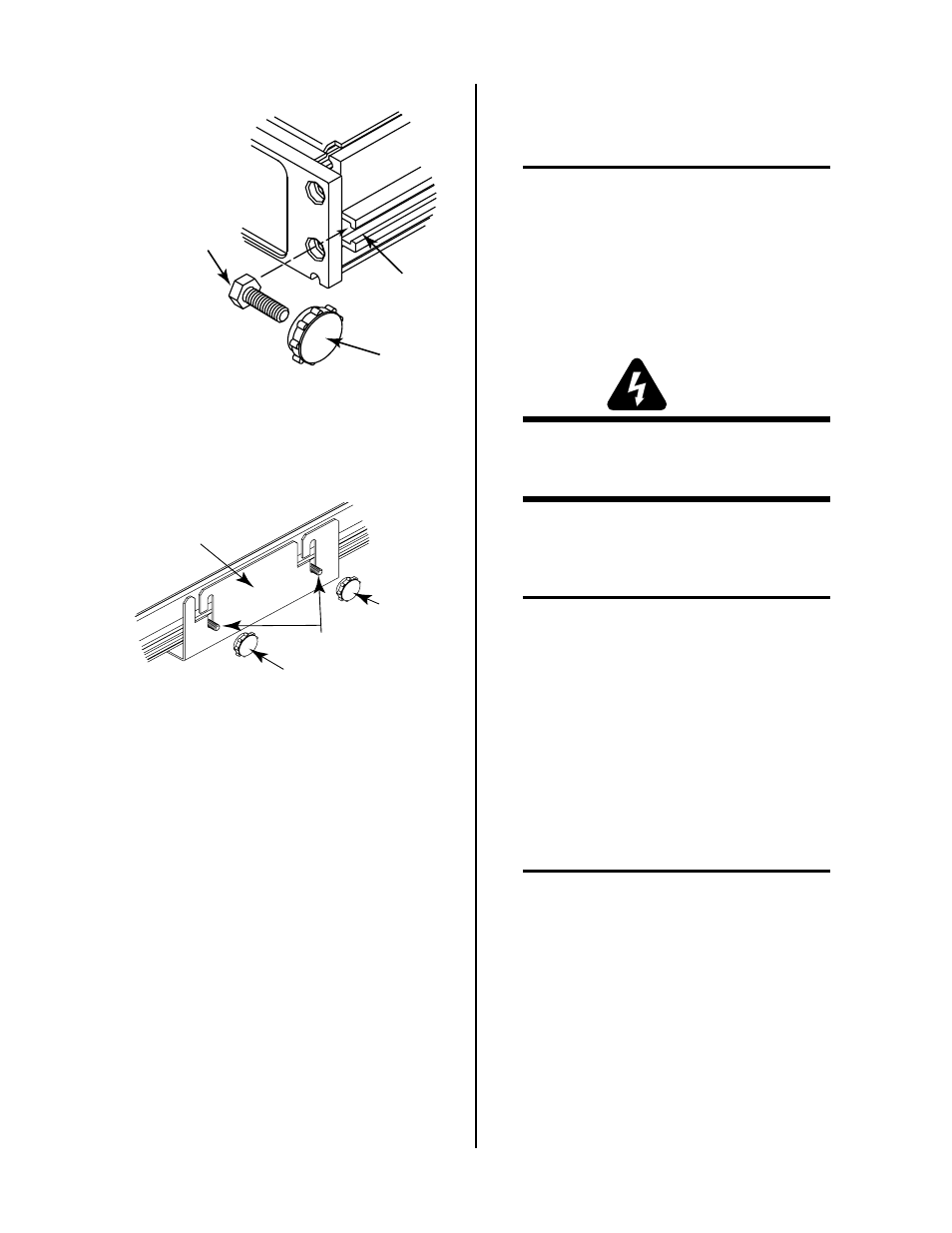
Slot
Hex Head Bolt
#10-32 x 3/8"
Knob
A-01125
Figure 3-4 Bolt Installation
4. Set the assembled units into the Mounting Bracket
being sure the four bolts are in the mounting slots.
Knob
Hex Head
Bolts
Knob
Mounting Bracket
A-00674
Figure 3-5 Knob Installation
5. Place one knob on each of the bolts protruding from
the bracket slots.
6. The assembled units can be adjusted for the best
viewing angle. The units can be tilted up to 10°.
Adjust the viewing angle per the following:
a. Loosen the four knobs sercuring the assemblied
units to the Mounting Bracket.
b. Adjust the assembled units for the desired
angle.
c. Tighten all four knobs.
d. If the angle is not correct, loosen knobs, read-
just until proper viewing angle is found, and
retighten all knobs.