Tweco GC-3000 Gas Control User Manual
Page 18
INSTALLATION PROCEDURES
14
Manual 0-2477
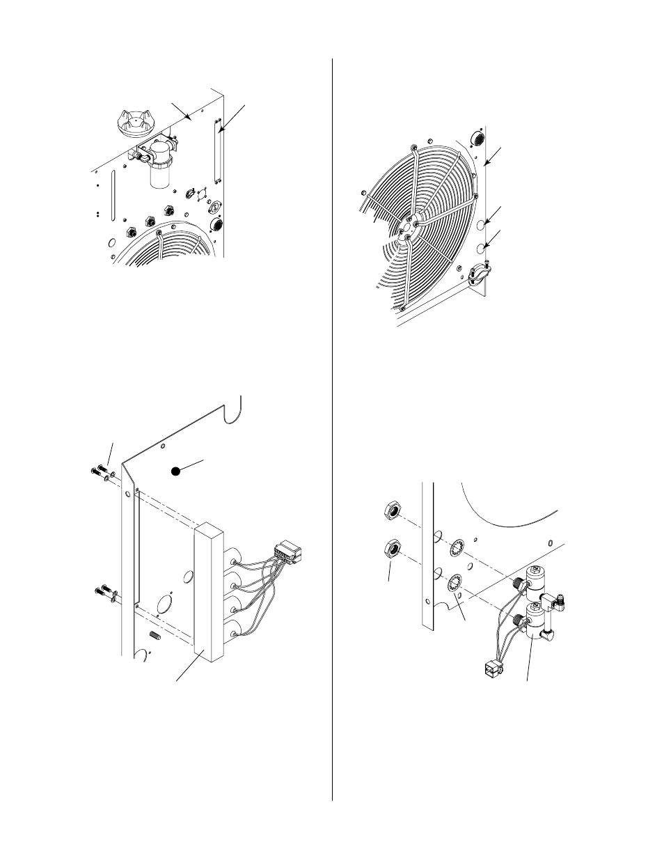
Power Supply
Rear Panel
Plasma Gas
Manifold Panel
A-01157
Figure 3-6 Plasma Gas Plate Location
2. Place the Plasma Gas Manifold Assembly into the cut-
out. The four solenoids should be towards the inside
of the Power Supply.
A-01156
Plasma Manifold
Mounting Screws
and Washers
(Four Places)
Power Supply
Rear Panel
Plasma Gas
Manifold Assembly
Figure 3-7 Plasma Gas Manifold Installation
3. Secure the Plasma Gas Manifold Assembly to the rear
panel with the screws removed in step 1.
B. Nitrogen (N2)/OTHER Secondary Gas
Assembly
1. Locate the two snap in plugs in the Nitrogen(N2)/
OTHER Gas cutouts on the Power Supply Rear Panel.
OTHER Secondary
Gas Supply Plug
N2 Secondary
Gas Supply Plug
A-01159
Power Supply
Rear Panel
Figure 3-8 Nitrogen (N2)/OTHER Gas Plugs
2. Using a screwdriver pry the two plugs from the Rear
Panel.
3. Place the two internal star washers over the ends of
the gas fittings on the two solenoid assemblies.
4. Place the assembly into the two holes making sure
that the elbow fitting is facing up.
A-01160
Nitrogen (N2) and
OTHER Secondary Gas
Solenoid Assembly
Internal Star
Washer
Hex Nut
Figure 3-9 Nitrogen N2)/OTHER Secondary Gas
Assembly Installation