04 cut quality, Cutmaster 42 – Tweco 42 CutMaster Operating Manual User Manual
Page 21
CUTMASTER 42
CUTMASTER 42
OPERATION 4-6 Manual 0-5141
Manual 0-5141 4-7 OPERATION
Drag Cutting With a Hand Torch
Drag cutting works best on metal 1/4"(6 mm) thick or
less.
NOTE
For best parts performance and life, always
use the correct parts for the type of opera-
tion.
A. Install the drag cutting tip and set the output
current.
B. The torch can be comfortably held in one hand
or steadied with two hands. Position the hand to
press the Trigger on the torch handle. With the
hand torch, the hand may be positioned close to
the torch head for maximum control or near the
back end for maximum heat protection. Choose
the holding technique that feels most comfortable
and allows good control and movement.
C. Keep the torch in contact with the workpiece during
the cutting cycle.
D. Hold the torch away from your body.
E. Slide the trigger release toward the back of the torch
handle while simultaneously squeezing the trigger.
The arc will start.
Art # A-09342
Trigger
Trigger Release
F. Place the torch tip on the work. The main arc will
transfer to the work.
NOTE
The gas preflow and postflow are a char-
acteristic of the power supply and not a
function of the torch.
3
4
Trigger
2
1
Trigger Release
Art# A-09341
G. Cut as usual. Simply release the trigger assembly
to stop cutting.
H. Follow normal recommended cutting practices as
provided herein.
3. Complete cutting operation.
NOTE
If the torch is lifted too far from the work-
piece while cutting, the main arc will stop
and the pilot arc will automatically restart.
4. Release the torch trigger.
a. Main arc stops.
5. Set the power supply ON / OFF switch to OFF (down
position).
a. AC indicator
turns OFF.
6. Set the main power disconnect to OFF, or unplug input
power cord.
a. Input power is removed from the system.
4.04 Cut Quality
NOTE
Cut quality depends heavily on setup and
parameters such as torch standoff, align-
ment with the workpiece, cutting speed, gas
pressures, and operator ability. Refer to
appendix pages for additional information
as related to the power supply used.
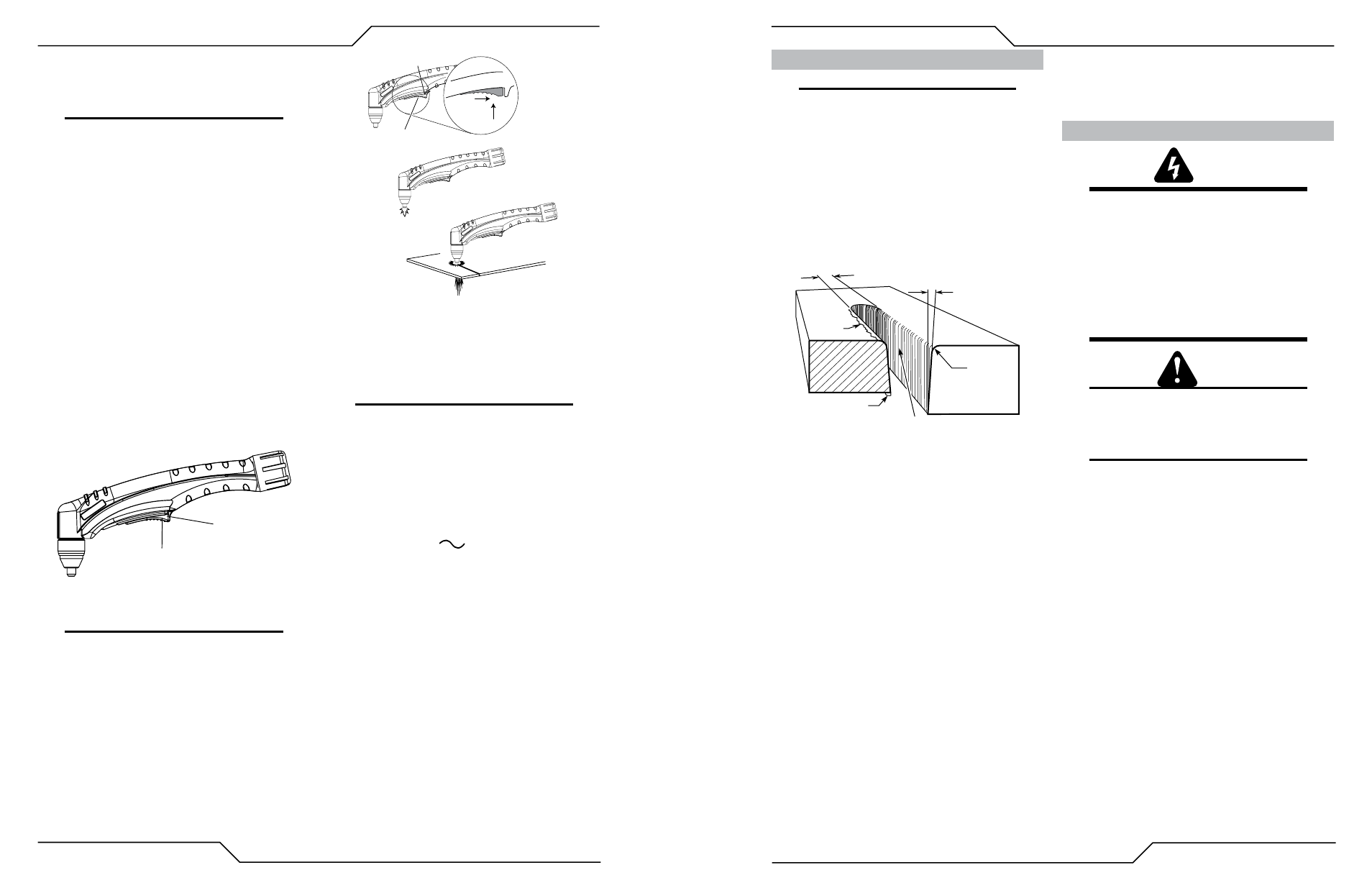
Cut quality requirements differ depending on application. For
instance, nitride build-up and bevel angle may be major fac-
tors when the surface will be welded after cutting. Dross-free
cutting is important when finish cut quality is desired to avoid
a secondary cleaning operation. The following cut quality
characteristics are illustrated in the following figure:
Kerf Width
Cut Surface
Bevel Angle
Top Edge
Rounding
Cut Surface
Drag Lines
Dross
Build-Up
Top
Spatter
A-00007
Cut Quality Characteristics
Cut Surface
The desired or specified condition (smooth or rough) of
the face of the cut.
Nitride Build - Up
Nitride deposits can be left on the surface of the cut when
nitrogen is present in the plasma gas stream. These build-
ups may create difficulties if the material is to be welded
after the cutting process.
Bevel Angle
The angle between the surface of the cut edge and a plane
perpendicular to the surface of the plate. A perfectly per-
pendicular cut would result in a 0° bevel angle.
Top - Edge Rounding
Rounding on the top edge of a cut due to wearing from the
initial contact of the plasma arc on the workpiece.
Bottom Dross Buildup
Molten material which is not blown out of the cut area
and resolidifies on the plate. Excessive dross may require
secondary cleanup operations after cutting.
Kerf Width
The width of the cut (or the width of material removed
during the cut).
Top Spatter (Dross)
Top spatter or dross on the top of the cut caused by slow
travel speed, excess cutting height, or cutting tip whose
orifice has become elongated.
4.05 General Cutting Information
WARNING
Disconnect primary power at the source be-
fore disassembling the power supply, torch,
or torch leads.
Frequently review the Important Safety Pre-
cautions at the front of this manual. Be sure
the operator is equipped with proper gloves,
clothing, eye and ear protection. Make sure
no part of the operator’s body comes into
contact with the workpiece while the torch is
activated.\
CAUTION
Sparks from the cutting process can cause
damage to coated, painted, and other sur-
faces such as glass, plastic and metal.
NOTE
Handle torch leads with care and protect
them from damage.
Torch Standoff
Improper standoff (the distance between the torch tip and
workpiece) can adversely affect tip life as well as shield cup
life. Standoff may also significantly affect the bevel angle.
Reducing standoff will generally result in a more square cut.
Edge Starting
For edge starts, hold the torch perpendicular to the work-
piece with the front of the tip near (not touching) the edge
of the workpiece at the point where the cut is to start.
When starting at the edge of the plate, do not pause at the
edge and force the arc to "reach" for the edge of the metal.
Establish the cutting arc as quickly as possible.
Direction of Cut
In the torches, the plasma gas stream swirls as it leaves
the torch to maintain a smooth column of gas. This swirl
effect results in one side of a cut being more square than
the other. Viewed along the direction of travel, the right
side of the cut is more square than the left.