Display and dip switches – tekmar 541 Thermostat User Manual
Page 2
© 2007
D 541 - 08/07
2 of 24
Table of Contents
Table of Contents ............................................................2
Display and DIP Switches ..............................................2
Dip
Switches
...........................................................2
Access
Levels
.........................................................3
Display and Symbols Description............................3
User
Interface
.........................................................4
Setup ..............................................................................5
View
Menu
.............................................................5
Adjust
Menu
............................................................6
Scene
Menu
............................................................8
Schedule
Menu
.......................................................9
Miscellaneous
Menu
..............................................9
Thermostat Operation .................................................. 11
Auxiliary Sensors ................................................. 11
Mode of Operation ............................................... 11
Adjusting the Temperature ................................... 12
Cycles Per Hour ................................................... 13
Heating Terminal Units ......................................... 13
Heating
Operation
................................................ 14
Cool
Groups
......................................................... 15
Setting the Schedule ............................................. 15
Optimum Start / Stop ........................................... 15
Scenes
................................................................. 16
Away Hold ............................................................ 17
Offset
................................................................... 17
Units of Temperature ............................................ 17
Backlight
.............................................................. 17
tN4
Address
......................................................... 17
Pump
Exercising
................................................... 17
Error Messages ............................................................ 18
Cleaning the Thermostat ............................................. 24
Warranty ....................................................................... 24
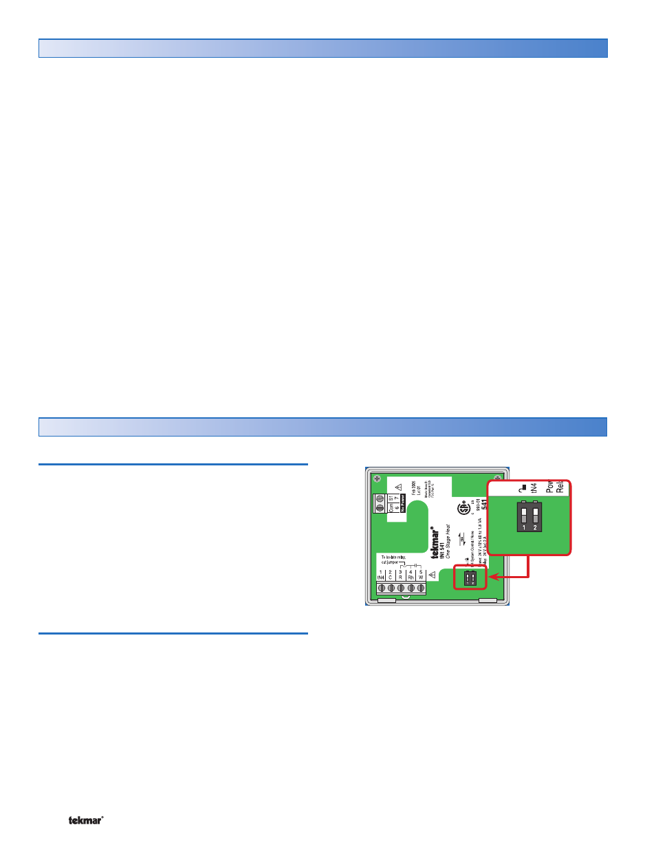
Display and DIP Switches
Dip Switches
tN4 System Control (DIP Switch #2)
A tN4 System Control is a control, not a thermostat, that
the 541 thermostat connects to through the tN4 bus. All
tN4 compatible Outdoor Reset Modules are tN4 System
Controls.
•
• If the thermostat is connected to a tN4 System Control,
set the tN4 System Control DIP switch to tN4 System
Control (down position).
•
• If the thermostat is not connected to a tN4 System
Control, set the tN4 System Control DIP switch to None
(up position).
Lock / Unlock (DIP Switch #1)
Use the Lock / Unlock DIP switch to lock or unlock the
Access Level of the 541.
•
• To unlock the Access Level, set the DIP switch to the
unlocked (down) position.
•
• To lock the Access Level, set the DIP switch to the locked
(up) position. Once locked, a padlock is displayed in the
lower right corner of the display and the Access Level
cannot be changed.
Note: The tN4 System Control’s Lock / Unlock DIP switch
overrides the Lock / Unlock DIP switch on the 541. Set
the tN4 System Control’s Lock / Unlock DIP switch to the
Unlock position before Access Levels can be changed on
the thermostat.