Sensor wiring, Front low voltage wiring diagram, Mounting the outdoor sensor – tekmar 401 House Control Installation User Manual
Page 6
© 2011
D 401 - 07/11
6 of 28
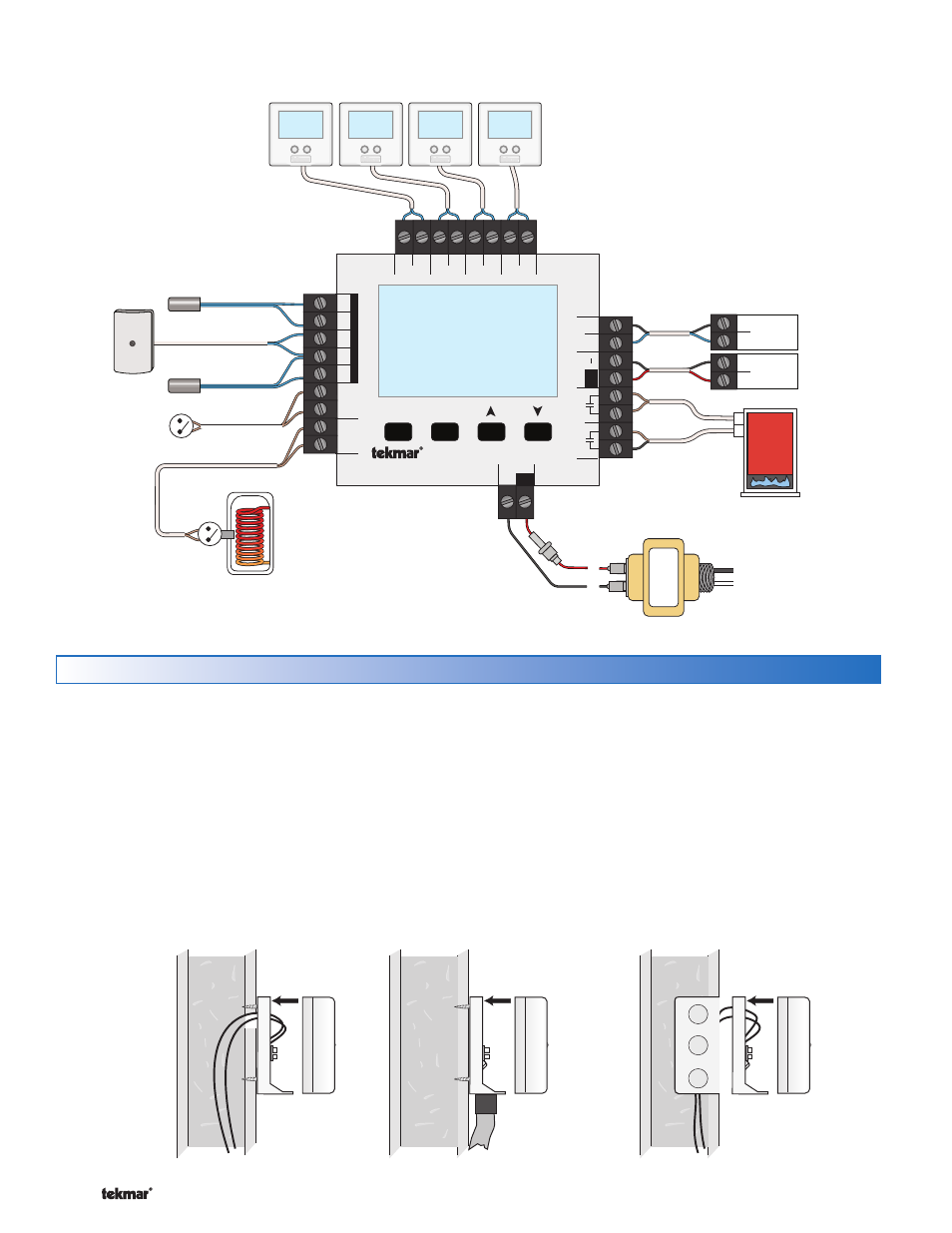
Front Low Voltage Wiring Diagram -------------------------------------------------------------------
-------------------------------------------------------------------
Sensor Wiring
Sensor with bottom
entry wiring
Sensor with rear
entry wiring
Sensor mounted
onto 2" x 4"
electrical box
R
C
L
N
Expansion
tN4 Boil
Ct
N
4
Modulating
Boiler
—+
2
1
WC
Back of
House Control 401
Menu
House Control 401
Item
+
Com
Boil
Out
DHW
Com
Zone 1
H8006B
Zone 2
Zone 3
Zone 4
tN2 tN2 tN2 tN2 tN2 tN2 tN2 tN2
Sensors - No P
ow
er
Call
Call
tN4
C
Mod dc/mA
Boil Exp.
Se
tpoint
DHW
R
C
Input Power
Made in Canada
Use at least 167°F
(75°C) conductors
Stage 2
Stage 1
24 V (ac) Transformer 009
DHW Call
from DHW
Tank Aquastat
(optional)
Setpoint Call
Outdoor
Sensor
070
Boiler Supply
Sensor 082
DHW Tank
Sensor 082
One or Two Stage
Boiler T-T
tekmarNet
®
2 Thermostats
tekmarNet
®
4 Expansion to
Wiring Centers, Timers, or
User Switch
Note: The temperature sensor (thermistor) is built into the
sensor enclosure.
Remove the screw and pull the front cover off the
enclosure.
The sensor can either be mounted directly onto a
wall or a 2” x 4” electrical box. When the senor is wall
mounted, the wiring should enter through the back
or bottom of the enclosure. Do not mount the sensor
with the conduit knockout facing upwards as rain could
enter the enclosure and damage the sensor.
•
•
In order to prevent heat transmitted through the wall
from affecting the sensor reading, it may be necessary
to install an insulating barrier behind the enclosure.
The Outdoor Sensor should be mounted on a wall
which best represents the heat load on the building (a
northern wall for most buildings and a southern facing
wall for buildings with large south facing glass areas).
The sensor should not be exposed to heat sources
such as ventilation or window openings.
The sensor should be installed at an elevation above
the ground that will prevent accidental damage or
tampering.
•
•
•
Mounting the Outdoor Sensor ------------------------------------------------------------------------
------------------------------------------------------------------------