Installation location, Rough-in wiring, Physical dimensions – tekmar 401 House Control Installation User Manual
Page 3: Materials required, Power required, Line voltage wiring
3 of 28
© 2011
D 401 - 07/11
Materials Required -----------------------------------------------------------------------------------
-----------------------------------------------------------------------------------
(2) #10 x 1” Wood Screws
(3) Wire Nuts
18 AWG LVT Solid Wire (Low Voltage Connections)
•
•
•
14 AWG Solid Wire (Line Voltage Connections)
tekmar 009K (24 V (ac) transformer with 4” x 4” junction box)
Cable or Conduit Connectors
•
•
•
Power Required --------------------------------------------------------------------------------------
--------------------------------------------------------------------------------------
115 V (ac), 1-phase, 15 A service from circuit breaker
panel
•
Power disconnect (optional)
•
Installation Location
When choosing the location for the control, consider the
following:
Keep dry. Avoid potential leakage onto the control.
RH 90% to 104°F (40°C).
Non-condensing environment.
Do not expose to operating temperatures beyond 32-
104°F (0-40°C)
Provide adequate ventilation.
Keep away from equipment, appliances or other
sources of electrical interference.
•
•
•
•
•
Locate the control near the pumps if possible.
Provide easy access for wiring, viewing and adjusting
the control.
Mount approximately 5 ft. (1.5 m) off the finished floor.
Install the electrical junction box to a wall using #10
x 1” wood screws. Wall anchors are recommended
when mounting to sheet rock wallboard or masonry.
•
•
•
•
Rough-In Wiring
Line Voltage Wiring-----------------------------------------------------------------------------------
-----------------------------------------------------------------------------------
The control operates a number of pumps through wiring
on the back of the control. The control must be mounted
to a 4” x 4” electrical junction box so that these electrical
connections are safely contained.
For ease of service, the circuit breaker or power disconnect
should be located in reasonably close proximity to the
equipment.
All line voltage wire connections are recommended to
be pulled inside a flexible or solid conduit. Always follow
proper wiring practices, building and electrical codes for
your jurisdiction.
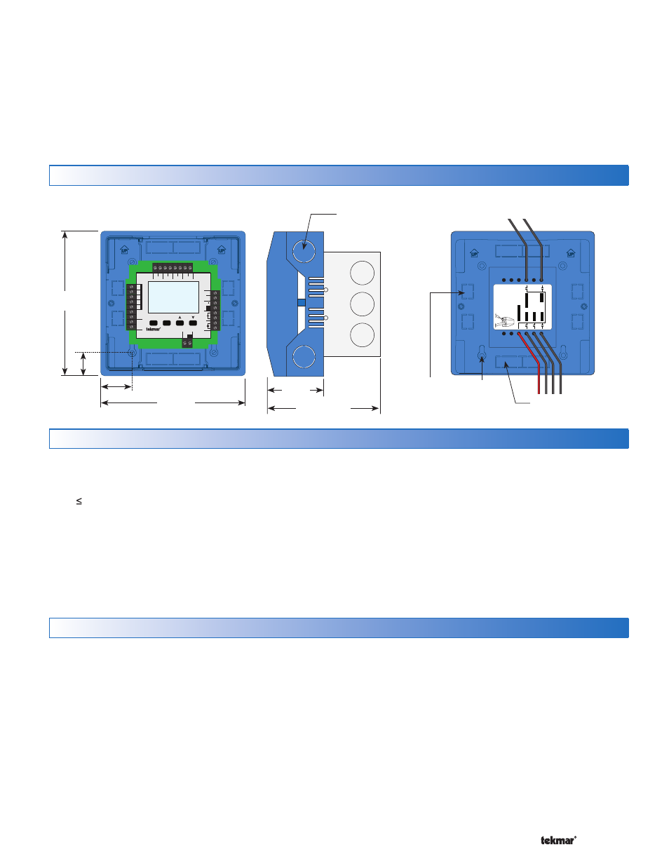
Physical Dimensions
Each cable must be pulled from the equipment to the
electrical junction box. It is recommended to label each
cable for easy identification. All line voltage wires should
be stripped to a length of 1/2” (13 mm).
Pull a three conductor 14 AWG cable for the following
equipment:
Circuit Breaker or Power Disconnect
DHW Tank Pump (if applicable)
Four Zone Pumps
•
•
•
Front View
Side View
Back View
5–1/2”
(140 mm)
5–1/2”
(140 mm)
1–1/8” (30 mm)
7/8”
(22 mm)
CL
1/2” Knock-out (x 4)
Control designed to mount on 4” x 4” electrical
box (not included). Electrical box shown
comes with tekmar 009K
2–1/4”
(57 mm)
4–1/2” (114 mm)
Menu
House Control 401
Item
+
Com
Boil
Out
DHW
Com
Zone 1
H8006B
Zone 2
Zone 3
Zone 4
tN2 tN2 tN2 tN2 tN2 tN2 tN2 tN2
Sensors - No P
ow
er
Call
Call
tN4
C
Mod dc/mA
Boil Exp.
Se
tpoint
DHW
R
C
Input Power
Made in Canada
Use at least 167°F
(75°C) conductors
Stage 2
Stage 1
40
1
Zone 4
Zone 3
Zone 2
Zone 1
DHW Pump
Pump P
ow
er
Strip wir
es 1/2 inch
(1
3 mm). Installed
wir
es ar
e no
t r
emo
vable.
12-1
8 A
W
G
Ø 1/8” (3 mm)
7/8” x 1/2” (23 mm x 12 mm)
Knock-out (x 4)
1/2” x 5/8”
(12 mm x 16 mm)
Knock-out (x 4)