Ng l n l – tekmar 401 House Control Installation User Manual
Page 5
5 of 28
© 2011
D 401 - 07/11
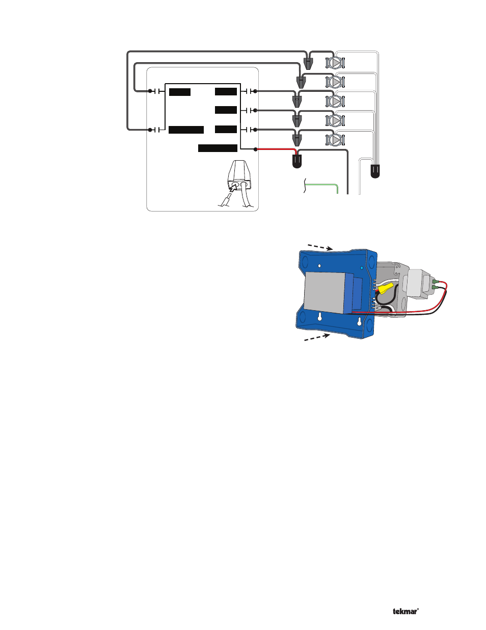
115 V (ac)
N
G L
N
L
(red)
(black)
(black)
(black)
(black)
(black)
to pump
grounds
Zone 2
Zone 3
Zone 4
DHW
Zone 1
401
Zone 4
Zone 3
Zone 2
Zone 1
DHW Pump
Pump Power
Strip wires 1/2 inch
(13 mm). Installed
wires are not removable.
12-18 AWG
Rear Line Voltage Wiring Diagram -------------------------------------------------------------------
-------------------------------------------------------------------
Ensure that the pump wires are neatly tucked inside
the electrical box.
Using 2 of the 4 holes in the back of the enclosure, se-
curely fasten it to the electrica junction box with 2 #10
screws as shown in Figure 5.
•
•
Install The Enclosure ---------------------------------------------------------------------------------
---------------------------------------------------------------------------------
Figure 5
External Power Supply
It is strongly recommended that a transformer with an in-line
fuse be used in order to protect the transformer from high
currents. The tekmar Transformer 009 includes a fuse.
Connect the 24 V (ac) leads from the transformer to the
C and R terminals marked “Input Power” on the 401.
tN2 Thermostats
The 401 is designed to operate with tekmarNet
®
2 Thermostats.
They provide the heating and cooling control for each zone,
and communicate with any other tekmarNet
®
device on
the system.
Connect the tN2 terminals from each thermostat to the
corresponding tN2 terminals for each zone on the 401.
tN4 Boiler Expansion Terminals
The 401 uses the Expansion tN4 and C terminals to
communicate with additional thermostats, setpoint controls,
wiring centers, and other tekmarNet
®
devices.
Connect the tN4 and C Boil Exp. terminals on the 401
to the corresponding tN4 and C Expansion terminals
of the additional external device.
Domestic Hot Water (DHW) or Setpoint Call
When the control receives a DHW Call or Setpoint Call for
heat it will override Outdoor Reset and Indoor Feedback
•
•
•
Low Voltage Wiring -----------------------------------------------------------------------------------
-----------------------------------------------------------------------------------
and operate the boiler to heat the DHW tank or the Setpoint
equipment.
To create a DHW call, wire a dry contact OR apply 24
V (ac) to the DHW call terminals.
To create a Setpoint call, wire a dry contact OR apply
24 V (ac) to the Setpoint call terminals.
Wiring the Boiler
The 401 can operate a single modulating boiler, single
on-off, or a single two-stage on-off boiler.
On/Off Boiler
Connect the Boiler Stage 1 terminals on the 401 to the
T-T (or R-W) terminals on the boiler.
If required, connect the Boiler Stage 2 terminals on the
401 to the second stage T-T (or R-W) terminals on the
boiler.
Modulating Boiler
Wire the Mod (dc/mA) positive (+) and negative (-) ter-
minals on the 401 to the input signal terminals on the
boiler. Correct polarity of the wires is important.
In some cases, the modulating boiler also requires
contact closure on the T-T terminals to fire the boiler. If
required, connect the Boiler Stage 1 terminals on the
401 to the T-T (or R-W) terminals on the boiler.
•
•
•
•
•
•