Testing the control, Error messages, Step seven operational test of control functions – tekmar 352 House Control User Manual
Page 7: Indicator lights "on, Step eight troubleshooting, Sensor and internal faults, Adjustment of settings, Step nine before you leave
Copyright © D 352 - 06/00
7 of 8
Testing the Control
STEP SEVEN
OPERATIONAL TEST OF CONTROL FUNCTIONS
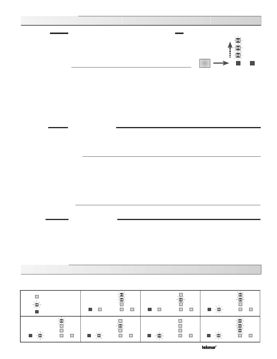
The main control functions on the 352 can be tested by pressing and holding the
Test button.
While the
Test button is pressed, the system pump and the Heat relay turn on. Once the Test
button is released the output relays return to normal operation. If an RTU is connected to
the control and the
Test button is pressed the UnOcc., WWSD, and the Min. Boiler / Max.
Supply lights will cycle on and off in an upward direction.
Indicator Lights "On"
Power
• 24 V (ac) power is applied to the control and the control is energized.
Heat Demand
• Heat is required in the system.
UnOcc.
• The control is in UnOccupied (Night Setback) mode.
WWSD
• Heat is not required in the heating system.
Min. Boiler /
• The supply water temperature is approaching the
Min. Boiler dial setting.
Max. Supply
• The system supply water temperature is approaching the
Max. Supply dial setting.
Pump
• The system pump is on.
Heat
• The relay contacts between
Heat — Heat (3 and 4) are closed.
STEP EIGHT
TROUBLESHOOTING
As in any troubleshooting procedure, it is important to isolate a problem as much as possible before proceeding. The Error Messages
and
Test button greatly simplify troubleshooting of the 352. When the control is flashing an error message, identify the fault from the
look-up table below and follow standard testing procedures to confirm the problem. If you suspect a wiring fault, return to steps three,
four and five and carefully check all external wiring and wiring connections.
Sensor and Internal Faults
• If an outdoor sensor fault occurs, the 352 will assume a fixed outdoor temperature of 32
°F (0°C), and will supply the appropriate
supply water temperature. An error message is displayed.
• If the RTU or Indoor Sensor short circuits, the 352 displays an error message and operates as if no RTU or Indoor Sensor is
connected.
• If a supply sensor fault occurs, the 352 displays an error message and turns the system pump and the
Heat relay off.
• If an internal control fault occurs, the 352 displays an error message. Press the
Test button to clear the error message. If the error
message remains, the control must be returned for repair.
Adjustment of Settings
• If the outdoor temperature is cold and the rooms are cold, increase the
Heating Curve dial setting by 0.1 per day.
STEP NINE
BEFORE YOU LEAVE
• Install the wiring cover over the wiring chamber and secure it with the screw provided.
• Place the front cover on the control to cover the setting dials and snap it into place.
• Place this brochure, and all other brochures relating to the installation, in the protective plastic bag supplied with the control.
• Place the bag in a conspicuous location near the control for future reference.
• It is important to explain the operation of this control within the system to the end user, and to anyone else who may be operating
the system.
Error Messages
Whenever a fault is detected in any of the sensors, the indicator lights will flash in specific ways to indicate the location of the problem.
For detailed Sensor and RTU testing instructions see Data Brochures D 070 and D 054.
Outdoor sensor
short circuit
Outdoor sensor
open circuit
Supply sensor
short circuit
Light off
Light flashing
Light on
Power
Pump
UnOcc.
Min. Boiler /
Max. Supply
WWSD
Heat
Pump
UnOcc.
Min. Boiler /
Max. Supply
WWSD
Heat
Supply sensor
open circuit
RTU 1
short circuit
Heat
Demand
Power
Heat
Demand
Pump
UnOcc.
Min. Boiler /
Max. Supply
WWSD
Heat
Power
Heat
Demand
Pump
UnOcc.
Min. Boiler /
Max. Supply
WWSD
Heat
Power
Heat
Demand
Pump
UnOcc.
Min. Boiler /
Max. Supply
WWSD
Heat
Power
Heat
Demand
RTU 1
open circuit
Pump
UnOcc.
Min. Boiler /
Max. Supply
WWSD
Heat
Power
Heat
Demand
Internal
fault
Pump
UnOcc.
Min. Boiler /
Max. Supply
WWSD
Heat
Power
Heat
Demand
Test
Pump
Heat
UnOcc.
WWSD
Min. Boiler /
Max. Supply