tekmar 352 House Control User Manual
Page 5
Copyright © D 352 - 06/00
5 of 8
• Run the wires from the 24 V (ac) power source or heat demand to the control mounting location.
Use a clean power source to ensure
proper operation.
• If a tekmar Timer 031 is used, follow the installation procedure provided in the Data Brochure D 031 and run the wiring back to the
control mounting location.
STEP FOUR
TESTING THE WIRING
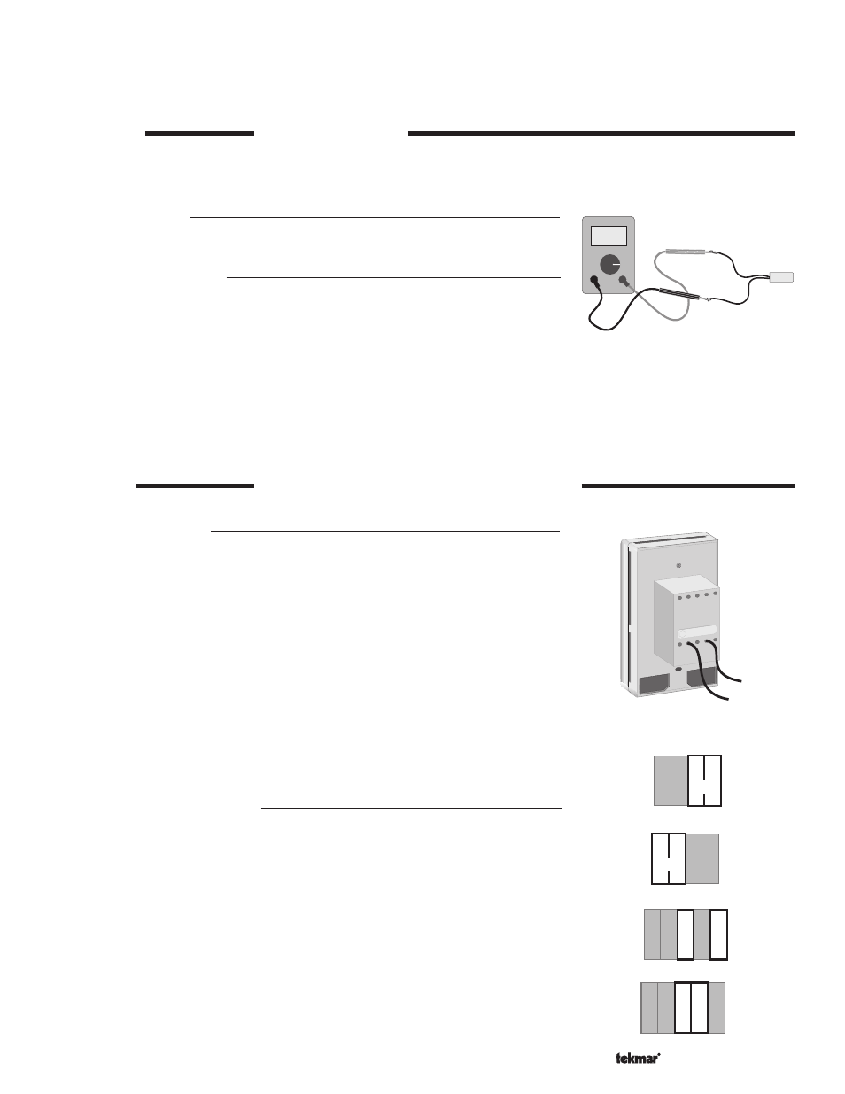
No wires should be connected to the control during testing.
A good quality electrical test meter, capable of reading from at least 0 — 200 V (ac) and at least 0 — 2,000,000 Ohms, is essential to
properly test the wiring and sensors.
Test the Sensors
Test the sensors and RTU according to the testing procedure in Data Brochures D 070
and D 054.
Test the Power Supply
Make sure exposed wires and bare terminals are not in contact with other wires or
grounded surfaces. Turn on the power and measure the voltage across the 24 V (ac)
power supply. The voltmeter should read between 22 and 26 Volts.
Test the Outputs
• Short the system pump wires and power up the pump circuit; the system pump should turn on. Remove the power from the system
pump circuit.
• If the control is in
Boiler mode, short the boiler wires and power up the boiler circuit; the boiler should fire. Remove the power from
the boiler circuit.
• If the control is in
Injection mode, short the valve wires and power up the valve circuit; the valve should open. Remove the power
from the valve circuit and the valve should close.
STEP FIVE
ELECTRICAL CONNECTIONS TO THE CONTROL
The installer should confirm that no voltage is present at any of the wires.
Output Connections
System Pump
Connect one of the wires from the system pump to one of the wires from the back of
the control. Connect the second wire from the back to the live (L) side of the 120 V (ac)
power source. The other wire on the system pump must be connected to the neutral
(N) side of the 120 V (ac) power supply. Refer to application brochures A 352.
Insert the low voltage wiring into the wiring chambers on the control and mount the 352
on the electrical box.
Heat Relay
If the DIP switch is set to
Boiler, connect the 120 V (ac) or 24 V (ac) boiler circuit directly
to the
Heat relay (3 and 4) terminals.
If an injection valve or pump is used, connect one of the wires from the valve or pump
to the
Heat relay (4) terminal and the other wire to the common or neutral side (C for
24 V (ac) or N for 120 V (ac)) of the power supply. Connect the
Heat Relay (3) terminal
to the live (R for 24 V (ac) or L for 120 V (ac)) side of the power supply.
Powered Input Connections
24 V (ac) Power
Connect the 24 V (ac) power supply to terminals
Power C— R (1 and 2) on the control.
Sensor and Unpowered Input Connections
Do not apply power to these terminals as this will damage the control.
Outdoor Sensor
Connect the two wires from the Outdoor Sensor 070 to the terminals
Com Sen — Out
Sen (7 and 9). The Outdoor Sensor measures the outdoor air temperature.
Supply Sensor
Connect the two wires from the Supply Sensor 071 to the terminals
Com Sen — Sup
Sen (7 and 8). The Supply Sensor measures the supply water temperature to the
system.
Ω
Ω
RTU
Sen
6
8
Sup
Sen
UnO
Sw
5
Com
Sen
7
Out
Sen
9
RTU
Sen
6
8
Sup
Sen
UnO
Sw
5
Com
Sen
7
Out
Sen
9
3 4
1 2
Power
Relay
Heat Heat
R
C
3 4
1 2
Power
Relay
Heat Heat
R
C
STOP
Refer se
rvicing to
qualified
personn
el. Open
ing voids
warranty
.
Pump
(black)
Live power
(black)