Settings, Room temperature unit (rtu) and indoor sensor, Unoccupied switch – tekmar 352 House Control User Manual
Page 6: Maximum system supply, Heating curve, Unoccupied temperature, Dip switch setting boiler — injection
Copyright © D 352 - 06/00
6 of 8
Room Temperature Unit (RTU) and Indoor Sensor
Connect the two wires from either the RTU 054 or the Indoor Sensor 076 to the
RTU Sen — Com Sen
(6 and 7) terminals. The RTU or Indoor Sensor provides indoor temperature feedback.
Unoccupied Switch
If an external timer or switch is used, connect the two wires from the external dry contact switch to the
UnO
Sw — Com Sen (5 and 7) terminals. When these terminals short together, the control registers an
UnOccupied signal. For more information on the tekmar Timer 031 consult its Data Brochure D 031.
Settings
Before adjusting the dial settings, read through the sequence of operation to ensure that you understand how the control operates.
STEP SIX
ESSENTIAL CONTROL SETTINGS
Minimum Boiler Supply
Most boilers require a minimum operating temperature to prevent corrosion from flue gas condensation. If the 352 is in
Boiler mode,
the
Min. Boiler Supply dial should be set to the lowest supply water temperature at which the boiler can operate without causing the
boiler flue gases to condense. Consult the boiler manufacturer for recommended minimum boiler supply temperatures. Some typical
settings are given below. If a condensing or electric boiler is used, the
Min. Boiler Supply dial should be set to Off.
Typical settings:
• Steel fire tube boilers …..........140 to 160
°F (60 to 71°C)
• Cast iron boilers …..................135 to 160
°F (57 to 71°C)
• Copper tube boilers ….............135 to 150
°F (57 to 66°C)
Maximum System Supply
If the 352 is used in
Injection mode, the 352 helps prevent the mixed supply water temperature from rising
above the
Max. Supply dial setting. The Max. Supply dial should be set to the maximum temperature allowed
in the system loop. There are many factors which may limit the allowable supply temperature in a radiant
floor heating system. A few of these are provided below.
• Some tubing manufacturers recommend that their products not be maintained at temperatures exceeding
140
°F (60°C). Consult the tubing manufacturer for specific details.
• No where in the concrete should the temperature be maintained above 170
°F (77°C).
• The surface temperature of a radiant floor heating slab should normally not exceed 85
°F (29°C). The slab surface temperature is
affected by the slab thermal resistance, the heating load, and the supply water temperature to the slab.
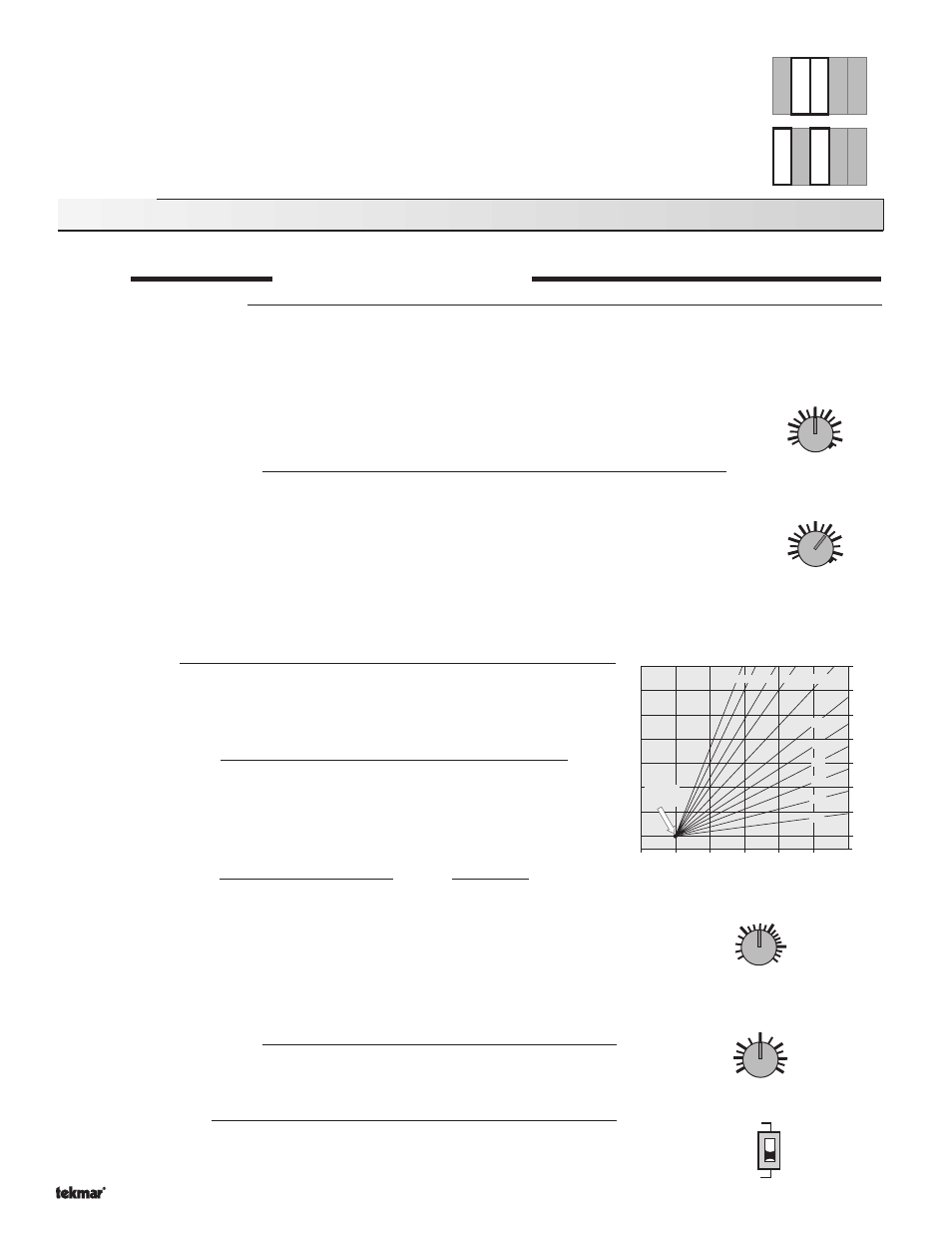
Heating Curve
The Heating Curve setting determines the number of degrees the supply water tempera-
ture is raised for every one degree drop in outdoor temperature. The
Heating Curve dial
position can be calculated from the following formula.
design supply temperature – desired room temperature
Heating Curve
=
desired room temperature – design outdoor temperature
Example: A system is designed to supply 120
°F water when the outdoor temperature is
10
°F. The desired room temperature is 70°F.
120
°F - 70°F (49°C - 21°C)
50
°F (28°C)
Heating Curve
=
=
= 0.8
70
°F - 10°F (21°C - (-12°C))
60
°F (33°C)
If the design supply water temperature is unknown, the
Heating Curve dial can be set to
a trial value using the typical design supply temperatures given below.
Typical design supply temperatures:
• Hydronic radiant floors … 100 to 130
°F (38 to 54°C)
• Baseboard convectors … 160 to 190
°F (71 to 88°C)
• Fan coils ………………… 180 to 210
°F (82 to 99°C)
Unoccupied Temperature
The
UnOccupied dial sets the desired indoor temperature during UnOccupied (Night
Setback) mode. If no indoor temperature feedback is used, the dial determines the
heating curve starting point during the UnOccupied period.
DIP Switch Setting
Boiler — Injection
If boiler operation is required, the DIP switch must be set to
Boiler. If mixing operation
is required, the DIP switch must be set to
Injection.
RTU
Sen
6
8
Sup
Sen
UnO
Sw
5
Com
Sen
7
Out
Sen
9
RTU
Sen
6
8
Sup
Sen
UnO
Sw
5
Com
Sen
7
Out
Sen
9
Outdoor air temperature
50
(10)
30
(-1)
10
(-12)
-10
(-23)
70
(21)
3.6 3.0 2.4 2.0
1.6
1.2
0.8
0.4
1.0
0.6
90
(32)
WWSD
Point
°F
(
°C)
Supply water temperature
110
(43)
70
(21)
90
(32)
210
(99)
170
(77)
150
(65)
130
(54)
190
(88)
0.2
0.2
2
3.6
1
3
Heating Curve
70
°F (21°C)
40 (4)
100 (38)
UnOccupied
Injection
Boiler
140
°F
170
Min. Boiler /
Max. Supply
105
Off
140
°F
170
Min. Boiler /
Max. Supply
105
Off