Step four, Step three – tekmar 269 One Stage Steam Control User Manual
Page 7
Copyright © D 269 - 06/00
7 of 12
Step Four
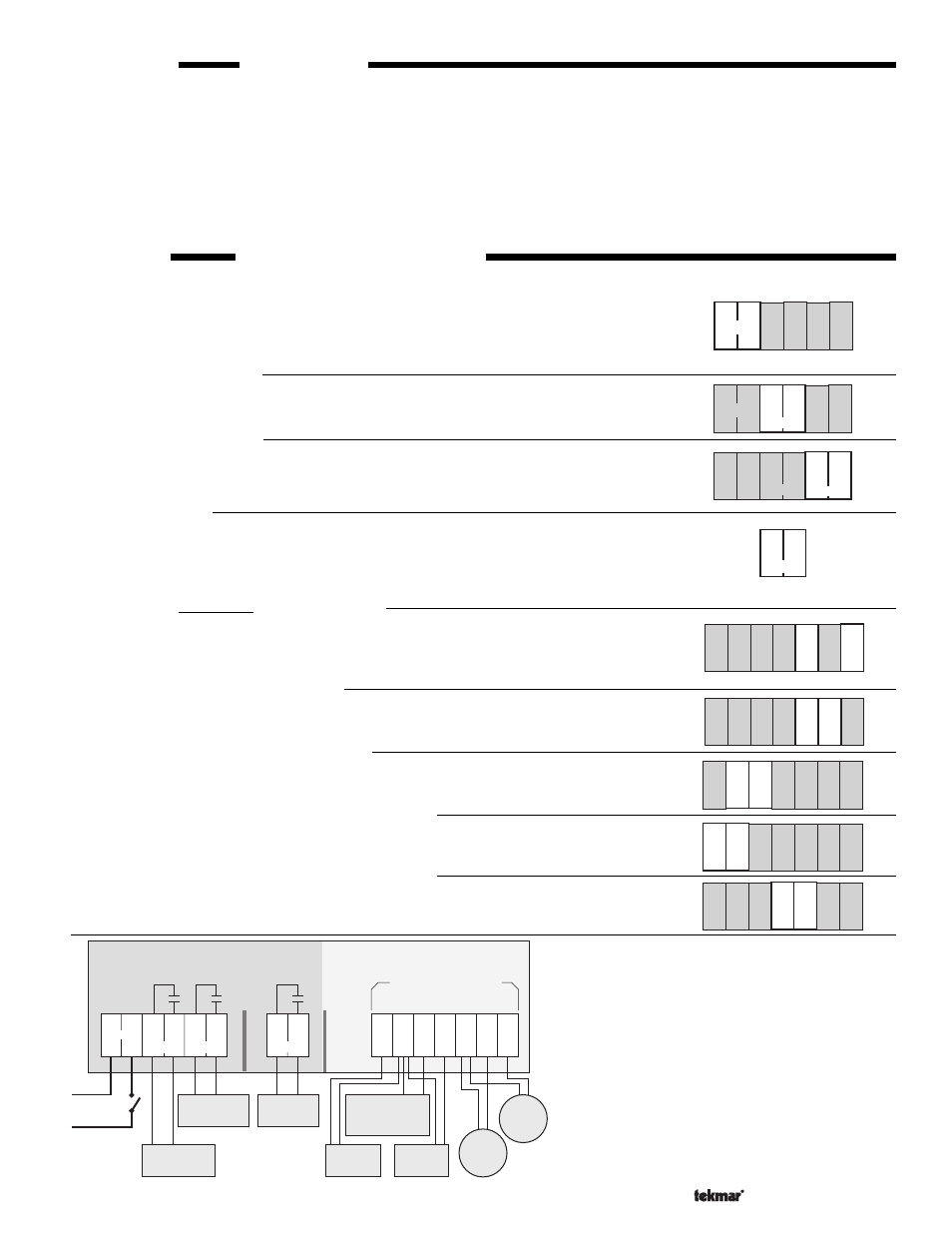
Electrical connection to the control
Power and output connections
The installer should test to confirm that no voltage is present at any of the wires.
• Install the control into the base, sliding it down until it snaps into place.
• All electrical connections are made directly to the plug terminals.
• Connect the 120 Vac power supply to terminals
N — L (1 and 2).
Warning relay connection
Connect the Warning device to terminals
Warn (3 and 4). These terminals lead to a dry
relay contact which closes when the control detects a sensor fault.
Step Three
Rough-in Wiring
All electrical wiring terminates in the control base wiring chamber. It has standard 7/8" (22mm) knockouts that will accept common
wiring hardware and conduit fittings. Before breaking out the knock-outs, check the wiring diagram and select those sections
of the chamber with common voltages, since the safety dividers will later prevent wiring from crossing between sections. Use
Nº 20 AWG to Nº 14 AWG copper wire rated for at least 60
°C and 300 volts.
Power should not be applied to any of the wires, during this rough-in wiring stage.
• Install the Outdoor Sensor 070, Condensate Return Sensor 071, according to the instructions in the Data Brochure D 001 and
run the wiring back to the control.
Option: Indoor Sensor(s) 074, can also be connected. See individual sensor instructions.
• Install the wiring from the other system components (Boiler, Warning device, Auxiliary device) to the base.
Auxiliary relay connection
Connect the Auxiliary device to terminals
Aux. (5 and 6). These terminals lead to a dry relay
contact which closes when the control is operating in manual mode, is not in WWSD, or the
Outdoor Sensor is short or open circuited.
Boiler connection
If the boiler has a 120 Vac control circuit, make sure the safety divider is installed in
the space between the boiler terminals and sensor terminals;
Connect the boiler circuit to terminals
Boiler (7 and 8). These terminals lead to a dry relay
contact which closes when the control requires boiler operation.
Outdoor Sensor connection
Connect the two wires from the Outdoor Sensor 070 to
Com Sen — Out Sen (13 and 15).
Condensate Return Sensor connection
Connect the wires from the Condensate Return Sensor (071) to terminals
Com Sen — Cnd Sen (13 and 14).
Option: Occupied/Unoccupied switch input
Connect the two wires from the Occupied/Unoccupied dry contact switch (eg. tekmar 030
Timer) to terminals
Com Sen — UnO Sw (10 and 11).
Option: Indoor temperature feedback Sensor Room 1
Connect the two wires from an Indoor Room Sensor 074 to terminals
10K S1 — Com Sen
(9 and 10).
Option: Indoor temperature feedback Sensor Room 2
Connect the two wires from an Indoor Sensor 074 to terminals
10K S2 — Com Sen
(12 and 13).
Sensor and unpowered input connections
Power should never be applied to these terminals. Damage to the control will result.
L
1
2
3
4
N
Aux.
5
6
Warn.
Power
L
1
2
3
4
N
Aux.
5
6
Warn.
Power
7
8
Boiler
L
1
2
3
4
N
6
Power
Warn.
5
Aux.
S1
14
12
Sw
9 10 11
10K
UnO
13
Sen
Com
S2
10K
Sen
Com
Sen
Cnd
15
Sen
Out
S1
14
15
12
Sw
9 10 11
10K
UnO
13
Sen
Com
S2
10K
Sen
Com
Sen
Cnd
Sen
Out
S1
14 15
12
Sw
9
10 11
10K
UnO
13
Sen
Com
S2
10K
Sen
Com
Sen
Cnd
Sen
Out
S1
14 15
12
Sw
9 10
11
10K
UnO
13
Sen
Com
S2
10K
Sen
Com
Sen
Cnd
Sen
Out
type 269
10A
10A
7
8
Boiler
120 Vac
Power
Supply
9
10
11
12
13
10K
S1
Com
Sen
10K
S2
UnO
Sw
Com
Sen
14
Cnd
Sen
15
Out
Sen
1
2
3
4
Do not apply power here
N
L
Power
Maximum 120Vac
Safety Divider
Warn.
Aux.
10A
Warning Relay
closes to turn on
warning device
Auxiliary Relay
closes to turn on
auxiliary device
Boiler Relay
closes to turn
on boiler
Safety Divider
10K Indoor
Sensor 074
(optional)
10K Indoor
Sensor 074
(optional)
Unoccupied
Switch (optional)
to switch control to
Unoccupied mode
Con-
densate
Sensor
071
Outdoor
Sensor
070
5
6
Electrical connections to the terminal plugs of the
269 control. The control's relays are shown in their
"power down" condition.
Note: This is not a wiring diagram. For a
detailed wiring schematic of your specific
application, refer to the Application
Brochure A 269.
S1
14 15
12
Sw
9 10 11
10K
UnO
13
Sen
Com
S2
10K
Sen
Com
Sen Sen
Out
Cnd