Error messages – tekmar 269 One Stage Steam Control User Manual
Page 11
Copyright © D 269 - 06/00
11 of 12
If a Condensate Return Sensor has been installed, and the sensor has become either short circuited or open circuit, the control
will not operate with any Steam Established /lockout functions. The control will default to the "Min. On Time (%)" dial setting. The
warning relay will turn on to indicate there is a fault and the appropriate error lights will be flashing.
After any repair has been completed, press the Test button to allow the control to cycle through the test routine. This
will allow you to confirm that correct operation has been restored.
Step Nine
Before you leave
Install the wiring cover over the wiring chamber and secure it to the base with the two screws provided. Place the front cover
on the control to cover the setting dials and snap it into place. Install a lock if security is required.
Place this brochure and all other brochures relating to the installation in the protective plastic bag supplied with the control. Place
the bag in a conspicuous location near the control for future reference.
It is important to explain the operation and maintenance of this control and of the system to the end user and anyone else who
may be operating the system.
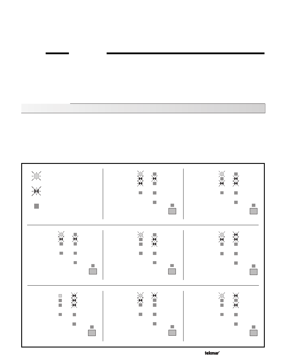
Light on continually
Light flashing
Light off
Indoor
Sensor S1
open circuit
(see trouble-
shooting
notes)
Indoor
Sensor S1
short circuit
(see trouble-
shooting
notes)
Outdoor
Sensor
open circuit
(see
trouble-
shooting
notes)
Indoor
Sensor S2
short circuit
(see
trouble-
shooting
notes)
Indoor
Sensor S2
open circuit
(see
trouble-
shooting
notes)
Outdoor
Sensor
short circuit
(see
trouble-
shooting
notes)
Condensate
Return
open circuit
(see
trouble-
shooting
notes)
Condensate
Return
short circuit
(see
trouble-
shooting
notes)
Error Messages
Whenever a fault is detected in any of the sensors, the indicator lights will flash in specific ways to indicate the problem and the Warning
relay will close to signal to the user that a fault has occurred.
The following look-up table describes each error condition and shows the flashing light sequence that results.
After repairing the problem, press the Test button to cycle the control through the test routine. This will confirm that the fault has been
repaired and that correct control action has been restored.
For detailed sensor testing instructions see Data Brochure D 001.
Test
Boiler
Power
Steam
Established
Heating
Cycle
UnOcc.
Auxiliary
WWSD
Early Start
Warning
Test
Boiler
Power
Steam
Established
Heating
Cycle
UnOcc.
Auxiliary
WWSD
Early Start
Warning
Test
Boiler
Power
Steam
established
Heating
cycle
UnOcc.
Auxiliary
WWSD
Early Start
Warning
Test
Boiler
Power
Steam
Established
Heating
Cycle
UnOcc.
Auxiliary
WWSD
Early Start
Warning
Test
Boiler
Power
Steam
Established
Heating
Cycle
UnOcc.
Auxiliary
WWSD
Early Start
Warning
Test
Boiler
Power
Steam
Established
Heating
Cycle
UnOcc.
Auxiliary
WWSD
Early Start
Warning
Test
Boiler
Power
Steam
Established
Heating
Cycle
UnOcc.
Auxiliary
WWSD
Early Start
Warning
Test
Boiler
Power
Steam
Established
Heating
Cycle
UnOcc.
Auxiliary
WWSD
Early Start
Warning