Connect or pin assignments – Sound Devices 664 User Manual
Page 67
Connector
Pin Assignments
Notes
(1) 5-Pin
Mixer Link I/O
1 – HP L
2 – HP R
3 – Mix R
4 – Mix L
5 – Link detection/Ground
Used to link the 664 to Sound Devices MixPre, MixPre-D,
302, 442, 552, or 664 Field Mixers. Mates with Sound
Devices XL-TA25, XL-35, and XL-TA55 optional accessory
cables. See Accessories for details. Custom cable note:
cable
must have shield connected to shell on both sides
and a 10K resistor from pin 5 to shield. See XL-TA55
documentation for details.
(1) 3.5 mm
Headphone
tip – signal L
ring – signal R
sleeve – signal ground
Mates with 3.5 mm TRS jack.
(1) 1/4-inch Female
Headphone
Made In
Reedsburg, Wisconsin
USA
www.sounddevices.com
This device complies with the
FCC Rules, Part 15, Class B.
1
2
3
4
5
6
7
8
788T
A
B
C
D
E
F
BFS
d
0
IN CF EX
ARM
ARM
BFS
d
0
INPUT
PWR
MENU
HDD
REC
R
L
KEYBD OUT
IN
C.LINK
AES I/O, GPIO, PWR
COMPACT FLASH
MENU
SELECT
1
2
3
4
5,6
UNBAL
ANALOG BAL LINE OUTS
FW800
FW400
USB
BAL AES
OUT
1,2
3,4
TIMECODE
SYNC
WORD / VID IN
DC IN
10-18V
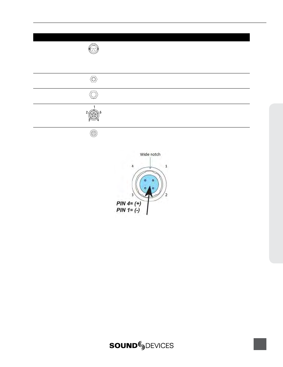
PIN 4
PIN 1
( )
( )
+
-
WORD OUT
tip – signal L
ring – signal R
sleeve – signal ground
Mates with 1/4-inch TRS jack.
(1) 5-pin LEMO
Time code
1 – ground
2 – SMPTE TC In
3 – ASCII in/out
4 – tuning out
5 – SMPTE TC out
LEMO B-series connector, pin assignments as viewed on
panel-mounted connector
(1) Hirose 4-pin
DC Input
1 – ground
2 – not connected
3 – not connected
4 – DC (+)
10-18 Volt DC input. Mates with Sound Devices XL-NPH
and XL-WPH3 powering accessories. See Accessories for
details. This is a floating supply, isolated from the mixer’s
ground. See below illustration for pin identification.
664 User Guide and Technical Information
61
Connect
or Pin Assignments