High-pass filter, Pan control, Input linking – Sound Devices 664 User Manual
Page 17: Pan control input linking
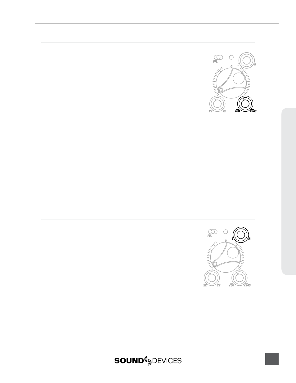
High-Pass Filter
Each input channel has an adjustable high-pass filter controlled by the
High-Pass Filter control. High-pass (or low-cut/low roll-off) filters are
useful for removing excess low frequency energy from audio signals.
Wind noise is a common unwanted low frequency signal that can be
reduced with the use of a high-pass filter. For most audio applications, en-
gaging the high-pass filter is beneficial, because audio information below
100 Hz is rarely used, especially for speech reproduction.
The 664’s high-pass filter circuit features an adjustable corner (-3 dB)
frequency over a range from 80 to 240 Hz. Below 80 Hz, the filter’s slope
is 12 dB/octave. At higher corner frequency settings, the slope is 6 dB/oc-
tave. The purpose for this compound slope is to give additional roll-off at
the 80 Hz setting to reduce wind noise and low frequency rumble. The higher settings can be used to
counteract the proximity effect of directional microphones where a more gentle slope is desired.
The 664’s high-pass filter circuit is unique because of its placement before any electronic amplifica-
tion. Most mixers’ high-pass filter circuits are placed after the microphone preamplifier, such that all
of the low-frequency signals get amplified. By virtue of the 664’s circuit cutting the low-frequency
signals before amplification, higher headroom is achieved in the presence of signals with significant
low-frequency energy.
When possible, attempt to equalize at the sound source with microphone selection, placement,
windscreens, and onboard microphone filtering. Many microphones have on-board high pass filters.
Use the high-pass filters on the 664 in conjunction with the microphone’s filter to increase the filter’s
slope.
The filter can be removed from the circuit completely by rotating the high-pass filter control to the
full counter-clockwise (detented) position. The high-pass filter potentiometer can be adjusted easily
and then recessed to hide it from the mixing surface.
Pan Control
The pop-up Pan Control routes inputs to the left (L) and right (R) chan-
nels of the stereo Master Bus. The pan pot has a detent in the center posi-
tion. After setting the pan, the pan control can be recessed to hide it from
the mixing surface during normal operation.
Input Linking
Input pairs 1-2, 3-4, and 5-6 can be linked as stereo pairs. When a pair of inputs is linked:
• Each channels’ Trim Control and High-Pass Filter Control work as normal, controlling coarse gain
and high-pass filtering for their respective inputs.
• The odd channel’s Input Fader controls the post-fade level of both inputs.
664 User Guide and Technical Information
11
In
put Se
tup & Contr
ol