Safe operating power, Excess power insufficient operating power – Kenco Engineering KMD Transmitter User Manual
Page 9
Page 9
4. Pull the power/signal wires through the conduit opening.
5. Connect the (+) and (-) wires to the plug. In the photo, the (+) connection is on the side facing the sensor
connection.
6. If this transmitter has (2) loops (interface or temperature measurement), repeat steps 3-5 for Loop #2. If the front
of the electronics “puck” does not have “Loop 2 Test” connections, do not connect any wires to the Loop #2
connector shown in the above photo.
7. Reinsert the electronics module. It only fits in one way, and it does not require much force to seat the puck into
the housing.
CALIBRATION
The Series KMD transmitter can be calibrated using the HART communications protocol, or by the optional keypad and
display. The keypad/display method has limited programming capability, as it is only capable of setting the zero & span
points of Loops 1 & 2. It can also test and adjust the LCD Display. Full access to all transmitter parameters is possible
through HART communications.
To calibrate the Model KMD with the onboard display/keypad, you must move the level/float to the zero and span
positions. Calibration via HART does not require you to move the level/float.
Setup Using Onboard Keypad and Display
This section covers the modes of operation and the steps necessary to calibrate the transmitter using the optional keypad
and display.
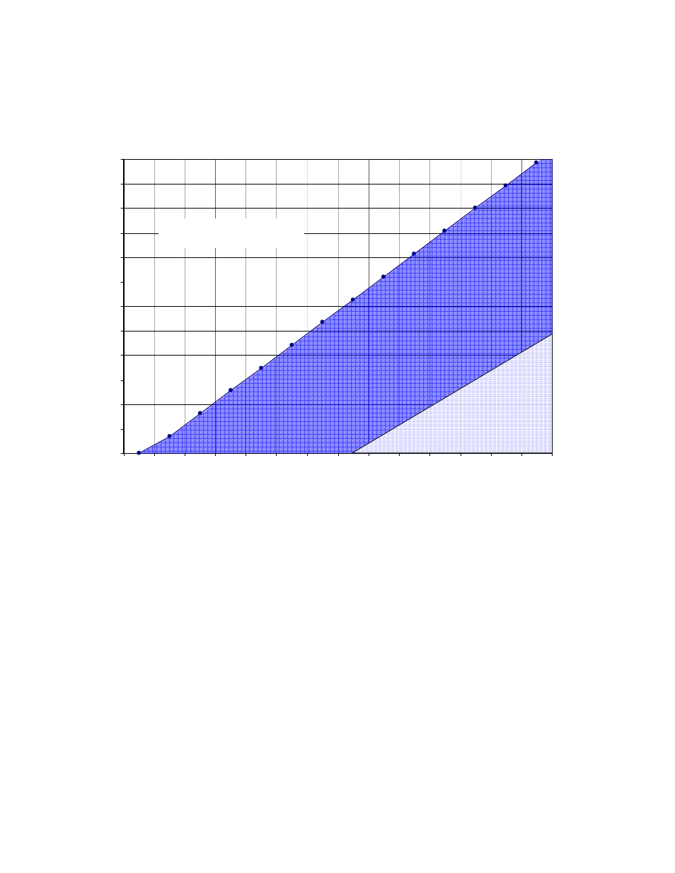
0
100
200
300
400
500
600
700
800
900
1000
1100
1200
10.5
12
14
16
18
20
22
24
26
28
30
32
34
36
DC Volts
R
e
s
is
ta
n
c
e
Ω
Safe Operating Power
Loop Resistance Chart
Excess Power
Insufficient Operating
Power