Kenco Engineering KMD Transmitter User Manual
Page 2
Page 2
GENERAL DESCRIPTION
The KMD Series Magnetostrictive Liquid Level Transmitters are designed for very high accuracy measurement of virtually
any liquid. The KMD can be used as a stand-alone transmitter to measure level and/or interface in a vessel, or can be
combined with the Kenco Series MLG Magnetic Gauge to provide a 4-20mA signal along with visual indication.
PRINCIPLE OF OPERATION
MODEL DESCRIPTION
KMD - 1 - B - - -
Output
Housing Type
Construction Material
Process Connection (Type)
Process Connection (Size)
RTD (must select Output Code 2)
Measurement Units
Sensor Length
Process Conn. (Size)
RTD
Measurement Units Sensor Length
Description
Code
Description
Code
Description
Code
Inches (xxx.x):
¾”
A
None
0
Millimeters
M
(20-300 inches)
1”
B
3” from Bottom Tip of Sensor
1
Inches
U
Millimeters (xxxxx):
1½”
C
Customer Specified Location
2
(508-7620 mm)
2”
D
2½”
E
3”
F
4”
G
6”
J
None
X
Output
Housing Type
Description
Code
Description
Code
In-Tank Single Loop
1
Single Cavity
B
In-Tank Dual Loop
2
Dual Cavity
C
MLG Version (Display)
3
Single w/ Display
D
MLG Version (no Display)
4
Dual w/ Display
E
Construction Material Process Conn. (Type)
Description
Code
Description
Code
316L SS
1
Swaged NPT
1
Hastelloy-C
3
Welded NPT
3
Teflon Sheathed 316L SS
A
150# Flange
6
300# Flange
7
600# Flange
8
None
X
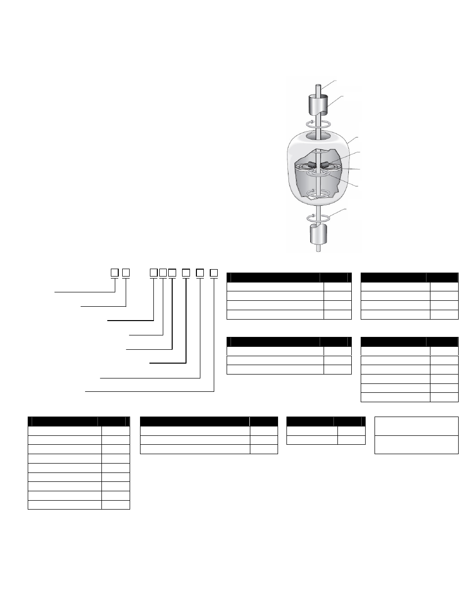
The Series KMD Transmitter will precisely sense the position of an
external float by applying an interrogation (electrical) pulse to the
waveguide. This pulse creates a magnetic field around the waveguide.
The magnets inside the float also have a magnetic field. Where the two
magnetic fields intersect, a rotational force is created (waveguide twist).
This “twist” creates a sonic pulse that travels along the waveguide.
The top of the sensing element houses the “pick-up” device that detects
the sonic pulse and converts it into an electronic pulse. The electronic
pulse is sent to the electronics module (puck), which calculates the time
difference between the transmission of the interrogation pulse and the
receipt of the sonic pulse. This time differential is used to determine the
exact position of the float, and is converted into a 4-20mA output signal.
When used with a Magnetic Level Gauge (MLG), the float is contained
in the MLG Chamber rather than on the Outer Pipe. However, the
theory is the same.
Waveguide
Outer Pipe
Float (moves
with liquid level)
Magnetic Field
(from float magnets)
Magnetic Field
(from interrogation pulse)
Waveguide “Twist”
Float Magnets