Kenco Engineering KMD Transmitter User Manual
Page 12
Page 12
Setup Using PC Setup Software
The transmitter can also be calibrated using a HART Modem and a PC. Kenco can supply software, at no charge, to
perform calibration by this method. Contact Kenco for more information.
The following parameters can be viewed / changed using this software:
Basic --
Manufacturing Information
Advanced --
Gauge Length, Gradient, Head Adder, Enable Display, Enable Loop 2, and Set Alarm Output
Calibration -- Level 1 Span and Offset (Zero), Level 2 Span and Offset, Temperature Span and Offset.
Output --
Level 1 Units of Measure, Level 2 Units of Measure, Temperature Units of Measure, Output Units of
Measure, Output Designations, and View Output Data.
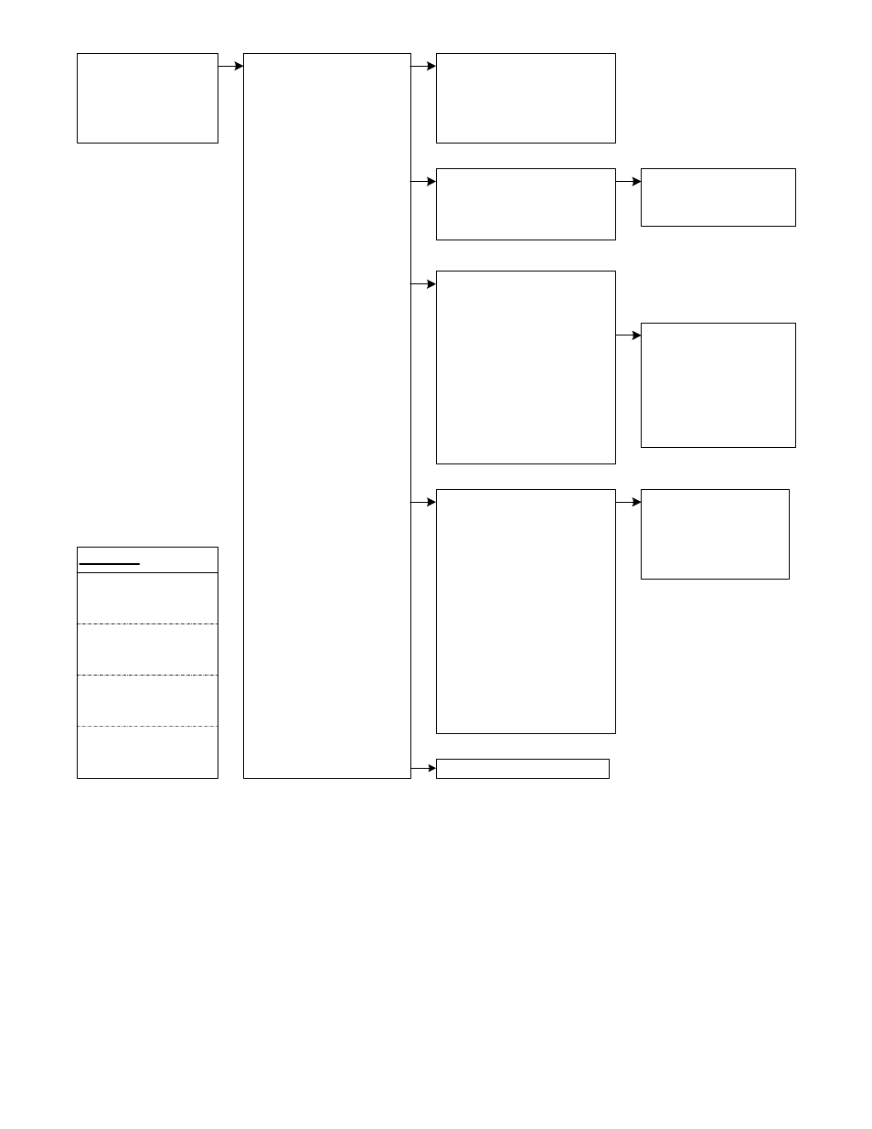
1 Device setup >>
2 *PV
3 *AO
4 *PV URV
5 *PV LRV
1 Process Vars >>
2 Diag/Service >>
3 Basic setup >>
4 Detailed setup >>
5 Review >>
1 View Measurements
2 View PV-Analog 1
3 View SV-Analog 2
4 View TV
5 View 4V
1 Level Range Cal >>
2 Self Test
1 Calibrate Level 1
2 Calibrate Level 2
3 Exit
1 #Tag
2 Eng unit
3 Range Values
4 Device Information >>
5 #Damp
1 Model Data
2 Comm Parameters
3 #Sensr s/n
4 Final asmbly num
5 Descriptor
6 Message
7 # Date
1 Instrument Config >>
2 Float Offset
3 #PV is
4 Change PV
5 #SV is
6 Change SV
7 #TV is
8 Change TV
9 #4V is
Change 4V
1 System Config
2 Sys Config 2
3 Gradient
4 #Length
5 #Head Adder
“Review all Parameters”
LEGEND
* Dynamic variable
at right
# Value displayed at
right
>> Submenu
Selection
Bold: Config/View in
submenu