Kenco Engineering KMD Transmitter User Manual
Page 5
Page 5
Complete the following steps to mount the sensor using the welded flange method:
1. Remove the Retaining Hardware. Install the float(s) onto the sensor. Remount the retaining hardware.
2. Insert the sensor into the vessel.
3. Attach the Sensor Flange to the Vessel Flange.
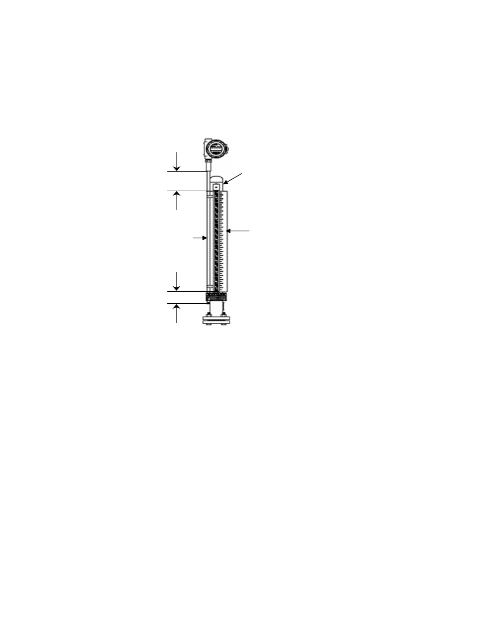
Magnetic Level Gauge (MLG) Mounting
The transmitter can also be used in conjunction with a Magnetic Level Gauge (MLG) to provide a 4-20mA output, as well
as visual indication of the level in the vessel. The MLG float contains a magnet which actuates the transmitter. The
transmitter is mounted alongside the MLG, and held in place by hose clamps. There is a minimum dead space of 3” at
the bottom and 3¾”at the top. Kenco adds an additional 3” to the top (total of 6¾”) for additional mounting flexibility.
Complete the following steps to mount the sensor to the MLG:
1. Open the hose clamps and place them around the MLG Chamber. Close the hose clamps, but leave them loose.
For transmitters less than 6ft. in length there are two hose clamps. For longer gauges, there is an additional hose
clamp for every 3ft. of length.
2. Mount the sensor alongside the MLG chamber, ±90° from the visual indicator. The sensor must be between the
hose clamps and the MLG Chamber.
3. Tighten the bottom hose clamp directly above the bottom hose clamp holding the visual assembly in place.
Tighten the top hose clamp directly below the top hose clamp holding the visual assembly in place. Starting at
the bottom, tighten any additional hose clamps 36” apart.
Wiring
It is recommended that conduit be installed onto the ¾” NPT connection on the electronics housing. A seal drain fitting
should be used to prevent moisture from entering the switch. In high humidity areas, use a breather drain to minimize
moisture intrusion
All wiring, conduit, and fittings must conform to local electrical codes for the location selected. If the transmitter is to be
used in a Hazardous Area, the applicable sections of the National Electric Code must be followed as well.
See the following page for the Hazardous area installation drawing. The barriers shown are not necessary for an
Explosion-proof installation.
3” Minimum
3¾”” Minimum
6¾” Standard
Magnetic Level Gauge
Transmitter
Visual Assembly