GBC Digicoil User Manual
Page 10
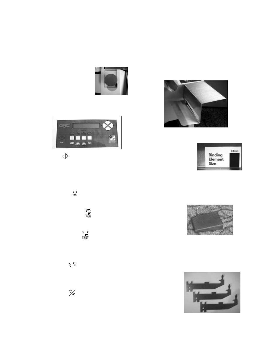
Power Switch
Located on the right side of the machine. This switch
turns electrical power on and off by push switch. The
LCD information display will illuminate when power is
on.
Emergency Stop Switch
(ESTOP)
The red switch located on the top
of the DigiCoil. This switch
should be pressed immediately
should any emergency occur. Pressing this switch cuts
off power to the motors in emergency situations. This
switch is only for emergency situations.
Keypad
Start Button
:
The green button on the Keypad.
This button, when pressed, starts initial operations of the
machine.
LCD Display: Located on the Keypad. The LCD
displays the machine status and faults.
Open Spines Button: Located on the Keypad.
When pressed, the Document Insertion Area opens and
the Spine Former Brackets lower.
Cut Crimp Manual Button: Located on the
Keypad. When pressed, the knives will cut and crimp
the properly placed document’s plastic coil.
Cut Crimp Setup Button: Located on the
Keypad. When pressed, the machine will insert the coil
into the document and the document is dropped down to
the Cut/Crimp station where the cycle ends for knife
adjustments.
Auto Cycle Button: Located on the Keypad. When
pressed, the machine will automatically complete each
binding cycle until there is no longer a coil present on
the Coil Driver area. The delay time is variable.
Stop/Reset Button: Located on the Keypad. When
pressed, the machine will power down and reset itself.
Service Arrows: Located on the Keypad. These are for
GBC Certified Service Technicians, and will produce no
effect when a user presses them – unless the operator is
setting the Auto Cycle Timer.
Staging Shelf
The silver metal shelf attached to the front of the
machine. The top of this shelf is to stack documents
waiting to be bound. The lower level shelf is meant to
hold coils being used for that specific binding job.
Binding Element Size Guide or Coil Size Guide
Located on the Staging
Shelf, this guide is used
to determine the
appropriate size of coil to
be used to bind a
document. This also
indicates the correct
Spine Former Size to be used in the binding process
.
Foot Switch
Connects to the rear underside of the machine. It is used
to begin each stage of each cycle, as directed by the
LCD.
Spine Former(s)
Located in the Storage Area. There are Formers ranging
in size from 8mm to 33mm, each measurement having
three in its set. They indicate how far the Document
Insertion Area closes to accommodate a document as
well as support the document while the coil is being
inserted. Each individual Spine Former has its
measurement
etched in the
metal for ease of
use. They are
inserted into the
Spine Former
Brackets.