Retract landing gear installation (optional) – E-flite Beechcraft Staggerwing 480 ARF User Manual
Page 9
9
E-flite Beechcraft 480 Staggerwing 480 ARF Assembly Manual
Retract Landing
Gear Installation (Optional)
Required parts
Bottom wing
Transmitter
Receiver
Receiver battery
Servo with hardware
Retract set
2-56 x 1/2-inch machine screw (2)
Landing gear assembly (right and left)
Landing gear door (right and left)
2mm x 5mm self-tapping countersunk screw (8)
Required Tools and Adhesives
Medium CA
Phillips screwdriver: #1
Pliers
Hobby knife with #11 blade
Ruler
Side cutters
Hobby scissors
Sandpaper
Hex wrench: 1.5mm Silicone adhesive
The landing gear can be left off of your model,
allowing you to hand-launch and belly-land the
airplane. If you choose to do so, skip the landing
gear installation and continue the assembly of your
model at the Horizontal Stabilizer Installation section.
1. Use a #0 Phillips screwdriver to remove the stock
servo horn from the servo. Center the aileron servo
using the radio system. Install the single-sided horn
so it is perpendicular to the servo centerline. Install
the screw to secure the horn using a #0 Phillips
screwdriver
2. Use pliers to bend the pushrod included with the
retracts so it measures 1
1
/
8
-inch (28mm) in length.
Use side cutters to trim the linkage so 1/4-inch (6mm)
extends past the bend.
3. Insert the Z-bend in the servo horn. The retract
servo is then installed in the wing with the output shaft
oriented towards the leading edge as shown using
a drop of medium CA. Don’t over-glue the servo in
case it requires removal in the future.
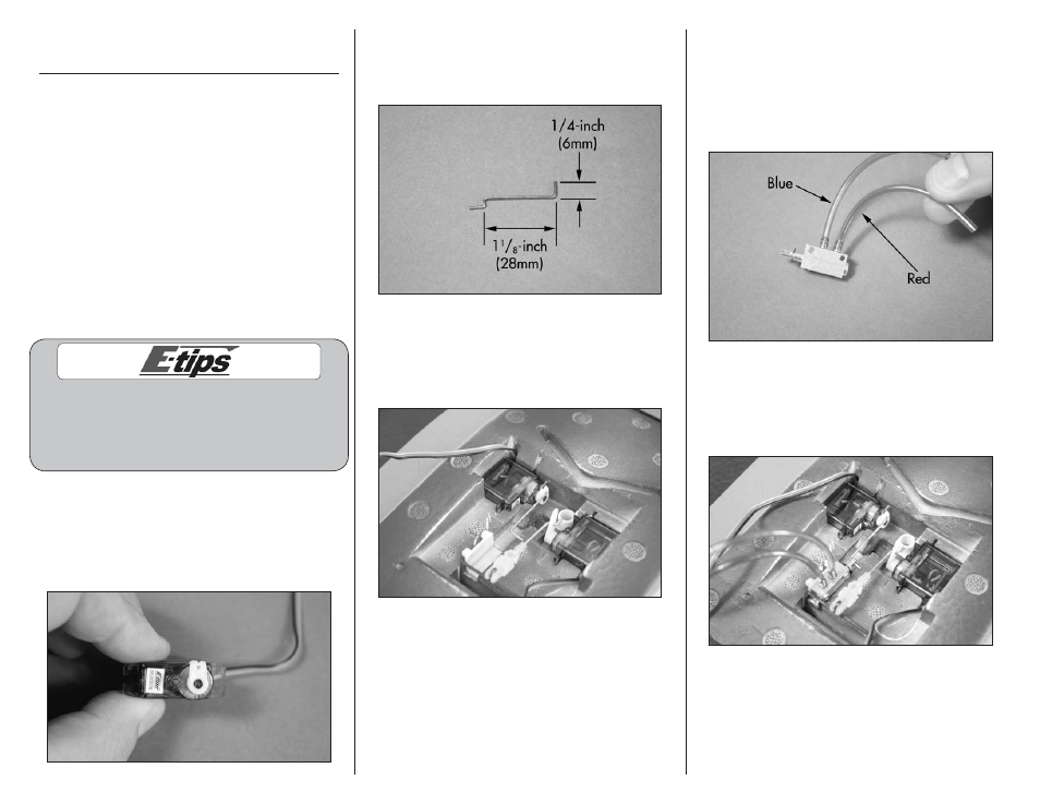
4. The nipples on the retract valve are offset slightly.
Below, it is visible that the stopper end of the valve
plunger orients TOWARDS the side where the nipple
is the closest. Cut a 3-inch section of red airline and
another of blue. These will be trimmed if required
later. Connect the blue air line to the left nipple and
the red airline to the right one as shown below.
5. Insert the end of the linkage in the hole of the
retract valve actuator. The valve is then secured
in the wing using two 2-56 x 1/2-inch machine
screws included with the retracts and a #1 Phillips
screwdriver.