Control throws – E-flite Beechcraft Staggerwing 480 ARF User Manual
Page 24
24
E-flite Beechcraft Staggerwing 480 ARF Assembly Manual
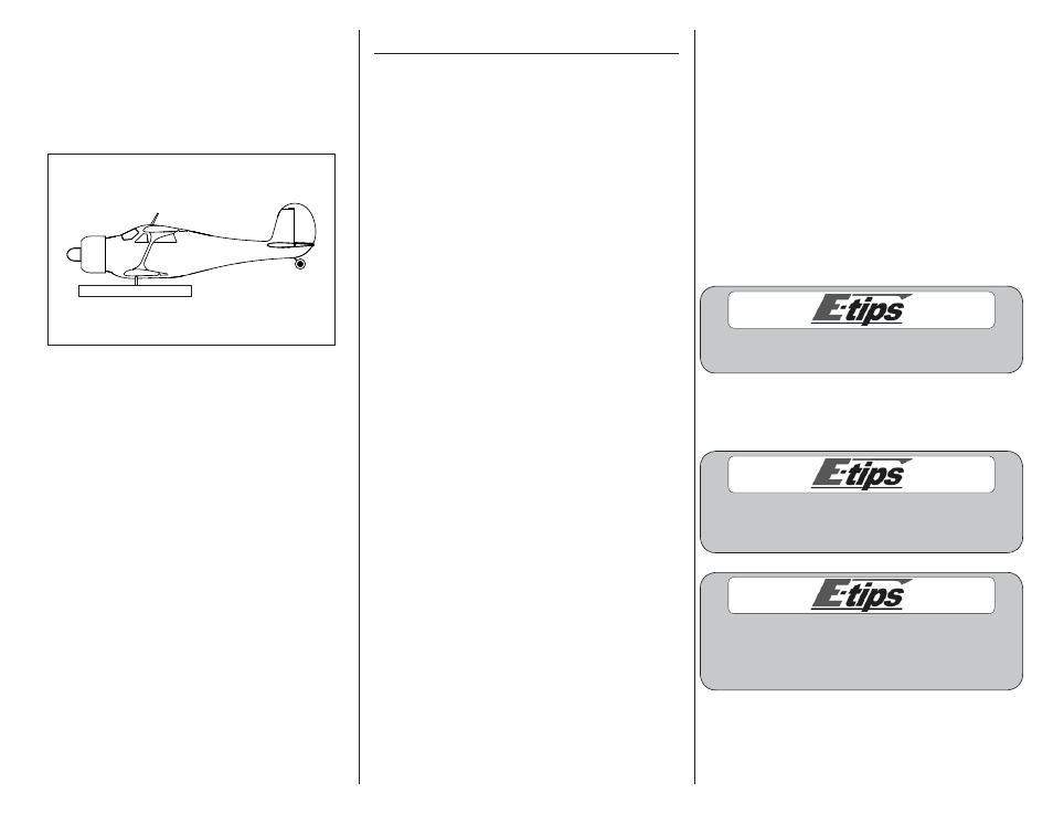
3. When balancing your model, support
the plane upright at the marks made on the
bottom of the lower wing with your fingers or a
commercially available balancing stand. This is
the correct balance point for your model. Make
sure your model is assembled and ready for
flight before balancing.
Balancing Stand
Adjust the motor battery as necessary so the model is
level or slightly nose down. This is the correct balance
point for your model. You should find the CG to be
very close with the battery installed as shown in this
manual. Mark the location of the battery on the battery
tray using a felt-tipped pen so it can be returned to this
position if it is removed from your model.
After the first flights, the CG position can be adjusted
for your personal preference.
Control Throws
1. Turn on the transmitter and receiver of your
model. Check the movement of the rudder using
the transmitter. When the stick is moved right, the
rudder should also move right. Reverse the direction
of the servo at the transmitter if necessary.
2. Check the movement of the elevator with the
radio system. Moving the elevator stick toward
the bottom of the transmitter makes the airplane
elevator move up.
3. Check the movement of the ailerons with the
radio system. Moving the aileron stick right makes
the right aileron move up and the left aileron
move down.
4. Use a ruler to adjust the throw of the elevator,
ailerons and rudder. Adjust the position of
the pushrod at the control horn to achieve the
following measurements when moving the sticks to
their endpoints.
Aileron
High Rate
Up:
1/2-inch
13mm
15% Expo
Down:
1/2-inch
13mm
15% Expo
Low Rate
Up:
13/32-inch 10mm
15% Expo
Down:
13/32-inch 10mm
15% Expo
Elevator
High Rate
Up:
21/32-inch 17mm
15% Expo
Down:
21/32-inch 17mm
15% Expo
Low Rate
Up:
1/2-inch
13mm
15% Expo
Down:
1/2-inch
13mm
15% Expo
Rudder
High Rate
Right:
3/4-inch
19mm
15% Expo
Left:
3/4-inch
19mm
15% Expo
Low Rate
Right:
21/32-inch 17mm
15% Expo
Left:
21/32-inch 17mm
15% Expo
Flap
Mid
3/16-inch
5mm
Full
13/32-inch 10mm
We found it unnecessary to add
any flap-to-elevator mixing during our
testing of the Beechcraft Staggerwing.
Measurements are taken at the inner or
widest point on the control surface.
These are general guidelines measured from our own
flight tests. You can experiment with higher rates to
match your preferred style of flying.
Travel Adjust and Sub-Trims are not listed
and should be adjusted according to each
individual model and preference.
We highly recommend re-binding the radio
system once all the control throws are set. This will
keep the servos from moving to their endpoints
until the transmitter and receiver connect.