Motor and speed control installation – E-flite Beechcraft Staggerwing 480 ARF User Manual
Page 18
18
E-flite Beechcraft Staggerwing 480 ARF Assembly Manual
Motor and Speed Control Installation
Required parts
Fuselage assembly Motor with hardware
Hook and loop tape Propeller
Spinner assembly
Electronic speed control (ESC)
3mm x 8mm machine screw (4)
3mm x 20mm machine screw (2)
Required Tools and Adhesives
Threadlock
Phillips screwdriver: #2
Hex wrench: 3/32-inch
1. Carefully remove the front windscreen cover from
the fuselage. Rotate the bottom of the cover forward
while removing it to prevent accidentally catching the
front seats inside the fuselage.
2. Remove the cowl from the fuselage. It is held in
position with a friction fit.
3. Pass the leads for the speed control through
the upper hole in the fuselage and into the motor
compartment as shown.
Always use threadlock on metal-to-metal fasteners
to prevent them from vibrating loose.
4. Use four 3mm x 8mm machine screws and a #2
Phillips screwdriver to attach the motor to the motor
mount. Note that the wires on the motor will face to
the top of the mount.
Matching the colors between the ESC and motor
when they are connected results in the correct
motor direction if using all E-flite components.
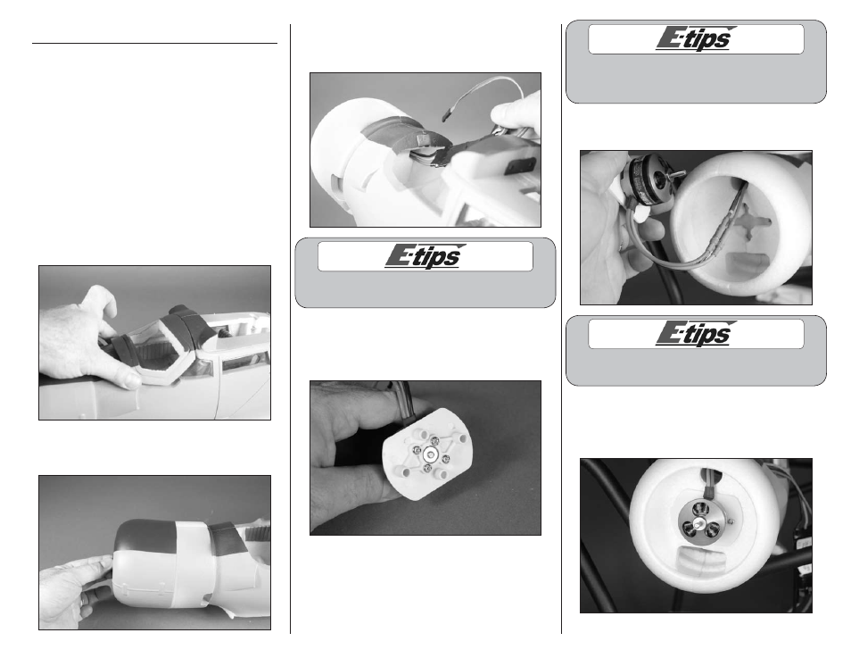
5. Connect the leads from the motor to the leads
of the ESC.
Always use threadlock on metal-to-metal fasteners
to prevent them from vibrating loose.
6. Guide the leads through the hole in the
fuselage. Use two 3mm x 20mm machine screws
and a #2 Phillips screwdriver to attach the motor
mount to the fuselage.