Control throws – E-flite Pitts Model 12 15e ARF User Manual
Page 32
32
E-flite Pitts Model 12 15e ARF Assembly Manual
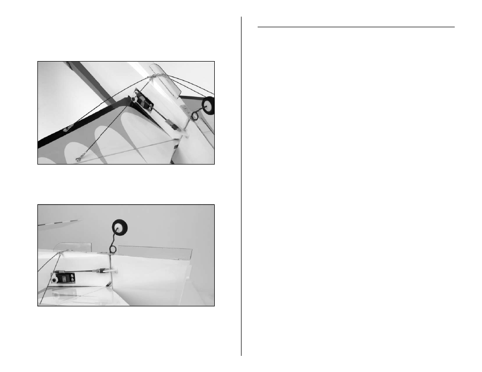
2. The flying wires are attached to the bottom of the
stabilizer using 2mm x 10mm machine screws. They are
then attached to the fuselage using two 2mm x 8mm
sheet metal screws.
3. Use medium CA to glue the lower fin extension to the
bottom of the fuselage.
Note: The clear fin extensions are included to enhance
the 3D flight envelope. Quique designed these and found
them to help the model in inverted harriers as well as
extreme yaw control during other high alpha manevers.
Control Throws
Use a ruler to adjust the throw of the elevator, ailerons and
rudder. Adjust the position of the pushrod at the control horn to
achieve the following measurements when moving the sticks to
their endpoints.
Note: Measurements are taken at the widest point on
the surface.
Ailerons
High Rate: 1
1
/
8
-inch (29mm) (Up/Down)
Low Rate: 1/2-inch (12mm) (Up/Down)
Elevator
High Rate: 1
3
/
4
-inch (44mm) (Up/Down)
Low Rate: 1-inch (25mm) (Up/Down)
Rudder
High Rate: 2
7
/
8
-inch (73mm) (Right/Left)
Low Rate: 1-inch (25mm) (Right/Left)
These are general guidelines measured from our own flight tests.
You can experiment with higher rates to match your preferred
style of flying.