Motor and speed control installation – E-flite Aeronca Champ 15e ARF User Manual
Page 11
11
E-flite Aeronca Champ 15e ARF Assembly Manual
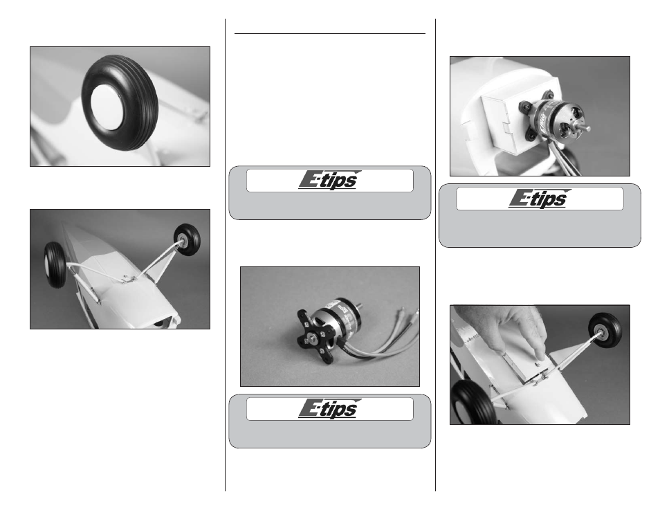
9. Place the hub cap back in position to complete
the wheel installation.
10. Repeat Steps 4 through 9 to install the
remaining landing gear strut and wheel.
Motor and Speed Control Installation
Required Parts
Fuselage assembly Cowling
Propeller
Motor battery (charged)
Speed control
Hook and loop tape
Transmitter
Receiver
#4 washer (4)
Motor with accessories
4-40 x 1/2-inch socket head screw (4)
2mm x 8mm sheet metal screw (4)
Required Tools and Adhesives
Low-tack tape
Ruler
Pin vise
Scissors
Card stock
Phillips screwdriver: #1
Thin CA
Hex wrench: 3/32-inch
Threadlock
Drill bit: 1/16-inch (1.5mm)
Make sure to use threadlock on all metal-to-
metal fasteners so they don’t vibrate loose.
1. Attach the X-mount to the back of the motor
using the screws provided with the motor. Use a #1
Phillips screwdriver to tighten the screws.
Make sure to use threadlock on all metal-to-
metal fasteners so they don’t vibrate loose.
2. Attach the motor to the firewall using four 4-40 x
1/2-inch socket head screws and four #4 washers.
Use a 3/32-inch hex wrench to tighten the screws.
The blind nuts in the firewall can be repositioned
for a variety of motors. It may be necessary to
move them for your particular motor installation.
3. Remove the battery/radio cover from the bottom
of the fuselage by pulling the catch rearward and
lifting the front of the hatch. The rear is held in
place using a tab.