E-flite F-16 400 DF ARF User Manual
Page 12
12
E-flite F-16 ARF Assembly Manual
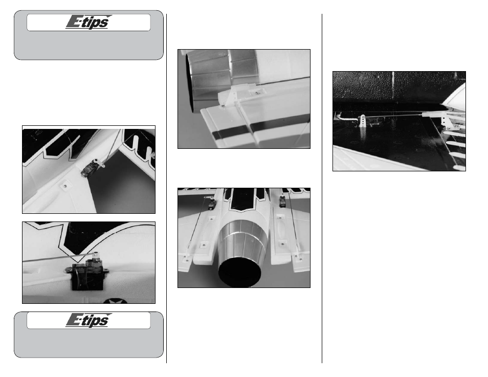
A water-based dark blue paint can be used to
paint the exposed white foam that is shown on
the wing where the servo lead runs through.
13. Insert the end of the 5
7
/
8
-inch (150mm)
pushrod wire with the clevis and “Z” bend
into the hole of the servo arm that is in one
hole from the end of the horn as shown. The
pushrod will enter from the top of the horn.
Insert the wire so it appears as shown in the
second image.
You may have to slightly enlarge the hole in the
servo horns for the pushrod wire. Use a pin drill
and 1/16-inch (1.5mm) drill bit to do so.
14. Attach the clevis on the pushrod to the
outer hole of the elevator control horn. Snap
the clevis together so it is secure on the
control horn.
15. Repeat Steps 13 and 14 to install the second
elevator linkage. The left and right linkages will be
mirror images of each other when installed.
16. Repeat Steps 13 and 14 to install the 2
7
/
8
-inch
(73mm) pushrod wire with clevis for the ailerons.
The end at the servo will attach to the outermost
hole in the aileron servo arm, and the clevis will
attach to the outer hole on the control horn as
shown. Make sure to install both the left and right
aileron linkages at this time.