Tail wheel installation and hinging the rudder – E-flite LR-1A Pogo ARF 15e User Manual
Page 8
14
E-flite LR-1A Pogo 15e ARF Assembly Manual
15
E-flite LR-1A Pogo 15e ARF Assembly Manual
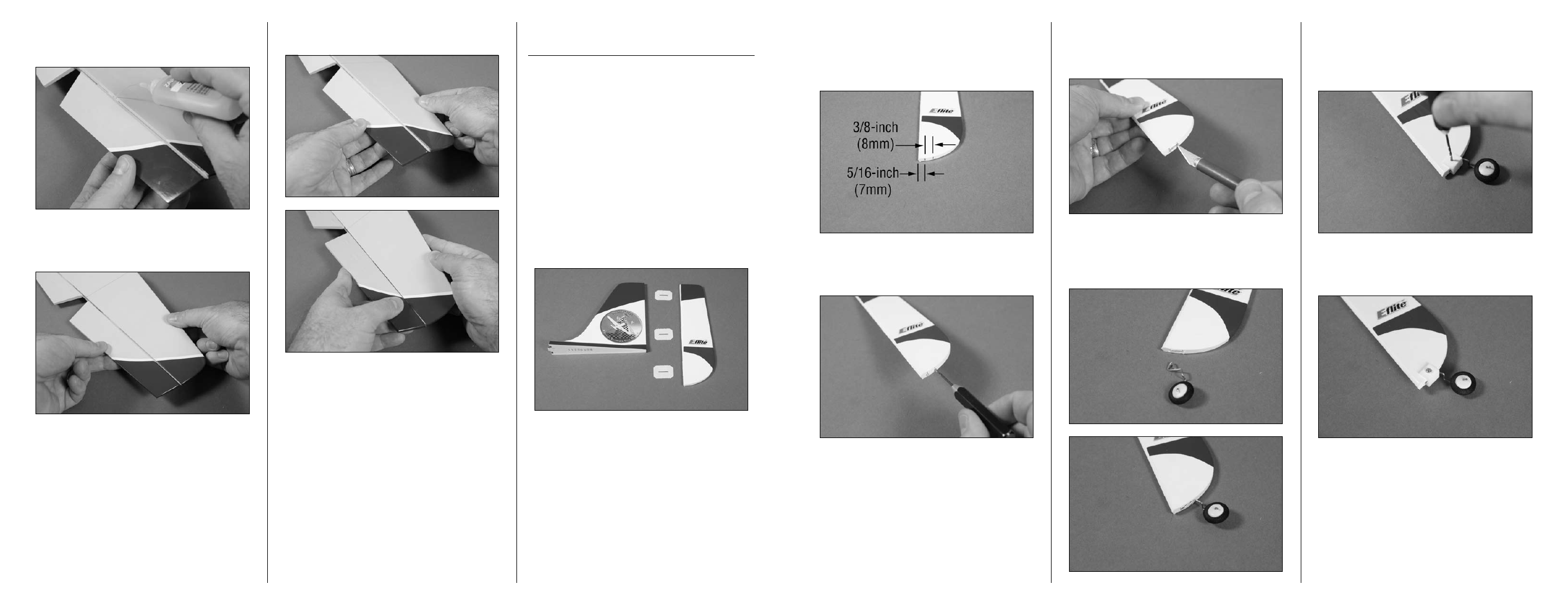
2. Use a felt-tipped pen to mark the bottom of the
rudder in preparation for the tail wheel assembly.
The first mark is 5/16-inch (7mm) behind the
leading edge of the rudder. The second mark is
3/8-inch (8mm) behind the first mark.
3. Use a pin vise and 1/16-inch (1.5mm) drill bit
to drill holes at the marks made in the previous
step. Make the holes 1/4-inch (6mm) deep.
4. Use a hobby knife with a #11 blade to cut a slot
that connects with the two holes so the tail wheel
assembly can be inserted into the bottom of the
rudder.
5. Check the fit of the tail wheel assembly into
the slot. The wire will fit flush to the bottom of the
rudder as shown. Once fit, use medium CA to glue
the tail wheel bracket in the slot.
6. Position the bracket over the tail wheel assembly.
With the bracket pressed tightly against the bottom
of the rudder, use a pin vise and 1/16-inch
(1.5mm) drill bit to drill a hole through the rudder
using the hole in the bracket as a guide.
7. Use a #1 Phillips screwdriver to install the 2mm
x 12mm sheet metal screw that holds the bracket in
position.
12. Press the elevators tightly against the stabilizer.
Apply thin CA into the top and bottom of all three
hinges.
13. Once the CA has fully cured. Gently pull on the
elevator to make sure the hinges are secure. If any
hinges are loose, reapply CA to the hinge.
14. Flex the elevator through its range of motion a
number of times to break in the hinges.
tail Wheel Installation and
hinging the Rudder
Required Parts
Rudder and fin assembly
Tail wheel assembly
2mm x 12mm sheet metal screw
Tail wheel bracket
Required tools and Adhesives
Pin vise
Drill bit: 1/16-inch (1.5mm)
Thin CA
Medium CA
T-pins
Phillips screwdriver: #1
Side cutter
Hobby knife with #11 blade
Felt-tipped pen
Medium CA
Ruler
1. Separate the rudder from the fin. Set the hinges
aside at this time.