Recommended racing setup, Optional accessories, Hinging the ailerons – E-flite LR-1A Pogo ARF 15e User Manual
Page 3: Using the manual, Covering colors, Recommended radio equipment, Required tools and adhesives, Recommended sport setup
4
E-flite LR-1A Pogo 15e ARF Assembly Manual
5
E-flite LR-1A Pogo 15e ARF Assembly Manual
Recommended Racing Setup
Motor:
Power 25 BL 1250Kv Outrunner
(EFLM4025B)
Speed Control:
60A Pro Switch-Mode BEC BL
ESC (EFLA1060)
Battery:
2500mAh 4S 14.4V 30C Li-Po
Battery (EFLB25004S30)
Spinner:
2-inch Aluminum Spinner
(EFLSP200)
Propeller:
8 x 8E (APC08080E)
optional Accessories
EFLA110
Power Meter
EFLC505
Intelligent 1- to 5-Cell
Balancing Charger
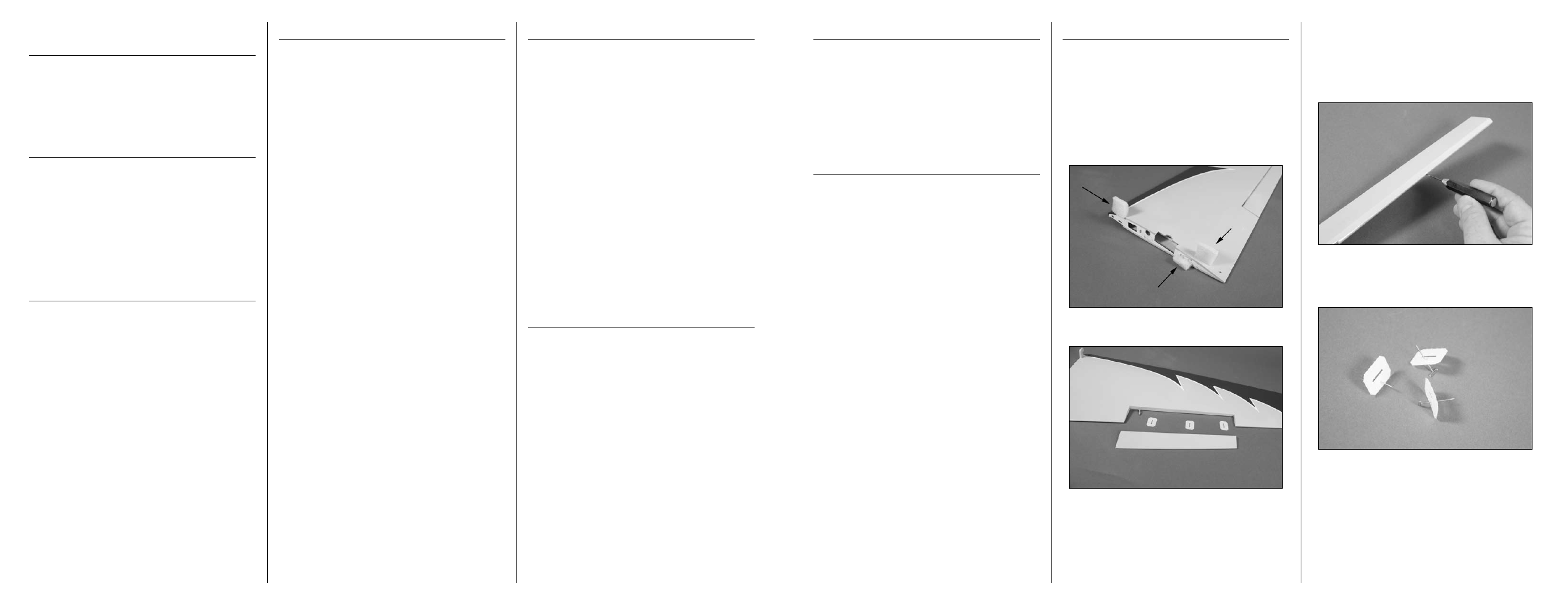
hinging the Ailerons
Required Parts
Left wing panel with aileron
Right wing panel with aileron
Required tools and Adhesives
T-pin
Thin CA
Pin vise
Drill bit: 1/16-inch (1.5mm)
1. Remove the foam protectors from the wing.
2. Remove the aileron from the wing panel.
3. Use a pin vise and 1/16-inch (1.5mm) drill bit
to drill a hole in the center of each hinge slot. Drill
holes in both the aileron and wing at this time. This
creates a tunnel for the CA to wick into, making
a better bond between the hinge and surrounding
wood.
4. Place a T-pin in the center of each of the three
hinges. This will center the hinges when installed in
the aileron.
Important Information
Regarding Warranty Information
Please read our Warranty and Repair Policy section
on Page 36 before building this product. If you as
the Purchaser or user are not prepared to accept the
liability associated with the use of this Product, you are
advised to return this Product immediately in new and
unused condition to the place of purchase.
Using the Manual
This manual is divided into sections to help make
assembly easier to understand, and to provide breaks
between each major section. In addition, check boxes
have been placed next to each step to keep track
of its completion. Steps with a single circle () are
performed once, while steps with two circles ( )
indicate the step will require repeating, such as for a
right or left wing panel, two servos, etc.
Remember to take your time and follow the directions.
Covering Colors
HANU870
White
HANU884
Cub Yellow
HANU885
Midnight Blue
Recommended Radio Equipment
You will need a minimum 4-channel transmitter,
receiver and four servos. You can choose to purchase
a complete radio system. If you are using an
existing transmitter, just purchase the other required
equipment separately. We recommend the crystal-
free, interference-free Spektrum
™
DX6i 2.4GHz DSM
®
6-channel system. If using your own transmitter, we
recommend the JR SPORT
™
MN48 Mini servos.
If you own a Spektrum radio, just add a DSM2
™
receiver
and three JR SPORT MN48 mini servos. We show the
installation of the AR6200 receiver in the manual.
transmitter
SPM6600
DX6i 6-Channel Full Range w/o
Servos MD2
or Purchase Separately
SPMAR6200
DSM2 AR6200 6-Channel
Receiver Ultralite
Servos
JSP20040
MN48 Mini Servo (3)
or
SPMSH5000
SH5000 High-Speed
Mini Servo (3)
Additional Items
JSP98100
3-inch (76mm) Servo
Extension (2)
Required tools and Adhesives
tools & Equipment
Drill
Epoxy brush
Felt-tipped pen
Flat blade screwdriver
Low-tack tape
Hook and loop strap
Light machine oil
Hook and loop tape
Long nose pliers
Mixing cup
Mixing sticks
Needle nose pliers
Paper towels
Pencil
Pin vise
Phillips screwdriver: #1, #2
Rubbing alcohol
Ruler
Sandpaper
T-pins
Side cutter
Square
Straight edge
Toothpicks
Open end or box wrench: 10mm
Hobby knife with #11 blade
Hex wrench or ball driver: 2.5mm, 3/32-inch, 3mm
Drill bit: 1/16-inch (1.5mm), 5/64-inch (2mm),
1/8-inch (3mm), 5/32-inch (4mm)
Adhesives
30-minute epoxy
Thin CA
Medium CA
Threadlock
Recommended Sport Setup
Motor:
Power 15 Brushless 975Kv
Outrunner (EFLM4015A)
Speed Control:
40A Pro Switch-Mode BEC BL
ESC (EFLA1040)
Battery:
3200mAh 3S 11.1V 30C Li-Po
Battery (EFLB32003S30)
Spinner:
2-inch Aluminum Spinner
(EFLSP200)
Propeller:
10 x 10E (APC10010E)
the Spektrum trademark is used with permission
of Bachmann Industries, Inc.