Control throws, Center of gravity – E-flite LR-1A Pogo ARF 15e User Manual
Page 17
32
E-flite LR-1A Pogo 15e ARF Assembly Manual
33
E-flite LR-1A Pogo 15e ARF Assembly Manual
After the first flights, the CG position can be adjusted
for your personal preference.
Control throws
1. Turn on the transmitter and receiver of your
model. Check the movement of the rudder using
the transmitter. When the stick is moved right,
the rudder should also move right. Reverse the
direction of the servo at the transmitter if necessary.
2. Check the movement of the elevator with the
radio system. Moving the elevator stick toward
the bottom of the transmitter makes the airplane
elevator move up.
3. Check the movement of the ailerons with the
radio system. Moving the aileron stick right makes
the right aileron move up and the left aileron move
down.
4. Use a ruler to adjust the throw of the elevator,
ailerons and rudder. Adjust the position of
the pushrod at the control horn to achieve the
following measurements when moving the sticks to
their endpoints.
Elevator high Rate
Up
3/8-inch
(10mm) 20% Exponential
Down
3/8-inch
(10mm) 20% Exponential
Elevator Low Rate
Up
1/4-inch
(6mm) 20% Exponential
Down
1/4-inch
(6mm) 20% Exponential
Aileron high Rate
Up
1/4-inch
(6mm) 15% Exponential
Down
3/16-inch (4.5mm) 15% Exponential
Aileron Low Rate
Up
3/16-inch (4.5mm) 15% Exponential
Down
5/32-inch (4mm) 15% Exponential
Rudder high Rate
Right
5/8-inch
(17mm) 30% Exponential
Left
5/8-inch
(17mm) 30% Exponential
Rudder Low Rate
Right
5/8-inch
(17mm) 45% Exponential
Left
5/8-inch
(17mm) 45% Exponential
Measurements are taken at the inner or
widest point on the control surface.
These are general guidelines measured from our own
flight tests. Use these for your first test flights. Later
you can experiment with higher rates to match your
preferred style of flying.
Travel Adjust and Sub-Trims are not listed
and should be adjusted according to each
individual model and preference.
Always use threadlock on metal-to-metal fasteners
to prevent them from vibrating loose.
8. Use the longer screw and washer to secure the
wheel and wheel pant to the landing gear. Use a
3mm hex wrench or ball driver to tighten the screw.
9. Repeat Steps 2 through 8 to install the remaining
wheel and wheel pant on the landing gear.
10. Secure the landing gear to the bottom of the
aircraft using two 1/4-20 x 2-inch nylon bolts. Use
a flat blade screwdriver to tighten the bolts.
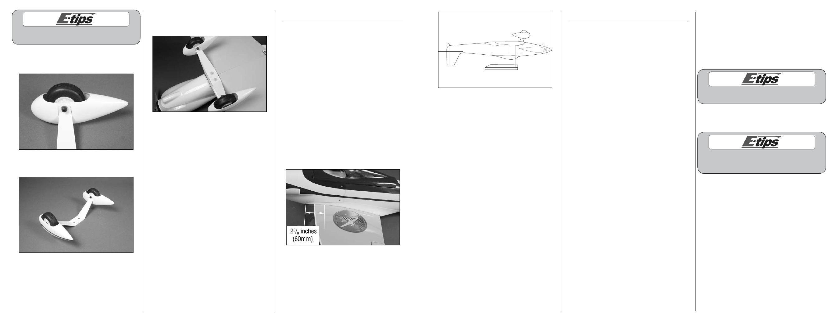
Center of gravity
An important part of preparing the aircraft for flight is
properly balancing the model.
Caution: Do not inadvertently skip this step!
The recommended Center of Gravity (CG) location
for your model is 2
3
/
8
inches (60mm) back from the
leading edge of the wing as shown with the battery
pack installed. Mark the location of the CG on the top
of the wing with a felt-tipped pen.
When balancing your model, support the plane
inverted at the marks made on the wing with your
fingers or a commercially available balancing stand.
This is the correct balance point for your model. Make
sure your model is assembled and ready for flight
before balancing.
Adjust the motor battery as necessary so the model is
level or slightly nose down. This is the correct balance
point for your model. You should find the CG to be
very close with the battery installed as shown in this
manual. Mark the location of the battery on the battery
tray using a felt-tipped pen so it can be returned to this
position if it is removed from your model.