Rudder and fin installation – E-flite LR-1A Pogo ARF 15e User Manual
Page 12
22
E-flite LR-1A Pogo 15e ARF Assembly Manual
23
E-flite LR-1A Pogo 15e ARF Assembly Manual
When cutting the covering make sure not to
cut into the underlying wood and weaken the
stabilizer. Another option is to use a soldering
iron or hot knife to melt the covering, rather than
cutting, to avoid damaging the stabilizer.
7. Remove the stabilizer from the fuselage. Use
a hobby knife with a new #11 blade to trim the
covering 1/16-inch (1.5mm) inside the line drawn
in the previous step.
8. Mix 1/2 ounce (15ml) of 30-minute epoxy.
Lightly brush epoxy on the stabilizer saddle.
9. Lightly brush epoxy on the exposed wood on the
bottom of the stabilizer.
10. Secure the stabilizer on the fuselage using
tape and a T-pin. Use a paper towel and rubbing
alcohol to remove any excess epoxy. Allow the
epoxy to fully cure before proceeding. Once cured,
remove the T-pin and tape from the stabilizer.
11. Once the epoxy has fully cured, remove the
wing from the fusealge.
Rudder and Fin Installation
Required Parts
Fuselage assembly
Rudder and fin assembly
Required tools and Adhesives
30-minute epoxy
Epoxy brush
Square
Felt-tipped pen
Mixing cup
Mixing sticks
Paper towels
Rubbing alcohol
Low-tack tape
Thin CA
Hobby knife with #11 blade
1. Slide the rudder and fin into position on the
fuselage. Make sure to guide the hinges into the
slot at the rear of the fuselage.
2. The fin keys into the fuselage at the front. It fits
tightly against the stabilizer when installed.
2. The rear of the wing is secured using two 4mm
x 30mm machine screws, two 4mm washers and
the wing bolt plate. Thread the first screw partially
to get the parts in alignment. Install the second
screw and tighten them both using a #2 Phillips
screwdriver.
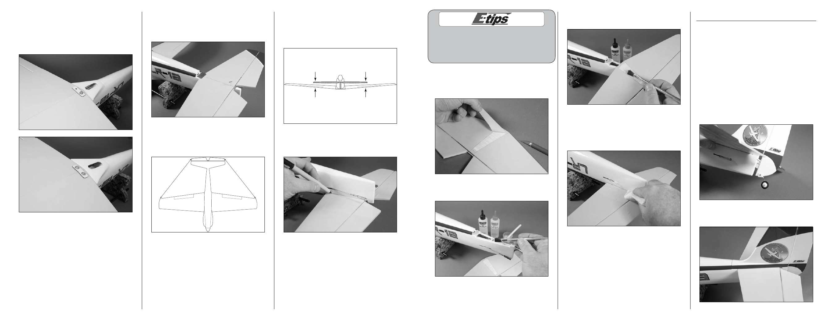
3. Place the stabilizer in position. Use a T-pin at the
rear of the stabilizer and tape at the front so it can
be positioned. The line drawn earlier will help in
setting the initial alignment.
4. Measure from each wing tip to corresponding
stabilizer tip. These measurements must match
exactly for the stabilizer to be in alignment. Remove
the tape and move the stabilizer if necessary.
A
A
A=A
5. Step back from the model 3–6 feet (1–2 meters)
and view the model from the rear. Check that the
wing and stabilizer are parallel with each other.
You might need to lightly sand the stabilizer saddle
to bring the wing and stabilizer into alignment.
Parallel
6. After the stabilizer has been aligned, trace
the outline of the fuselage on the bottom of the
stabilizer using a felt-tipped pen.