Rudder and elevator linkage connections – E-flite LR-1A Pogo ARF 15e User Manual
Page 14
26
E-flite LR-1A Pogo 15e ARF Assembly Manual
27
E-flite LR-1A Pogo 15e ARF Assembly Manual
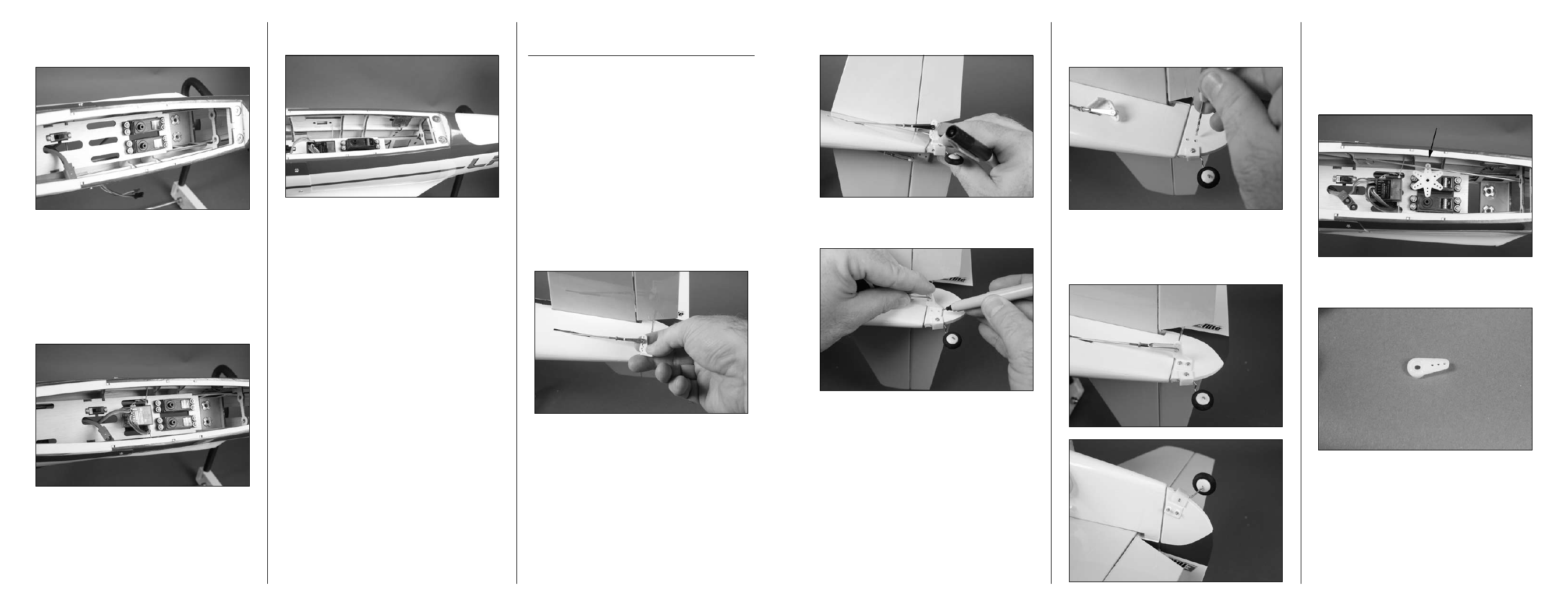
2. Position the horn on the rudder so the holes in
the horn align with the rudder hinge line.
3. Use a felt-tipped pen to transfer the location of
the control horn mounting screws to the rudder.
4. Use a pin vise and 5/64-inch (2mm) drill bit to
drill the two locations for the control horn mounting
screws.
5. Secure the control horn to the rudder using two
2mm x 12mm sheet metal screws and a control
horn backplate. Tighten the screws using a #1
Phillips screwdriver.
6. Use the radio system to center the rudder servo.
Install the servo horn so it is perpendicular to
the servo center line. The servo horn has an odd
number of splines, so rotate it until the arms are
aligned, rather than using the sub-trim function
from the radio. Use a felt-tipped pen to mark the
arm that aligns with the rudder pushrod.
7. Remove the horn and use a side cutter to remove
the arms from the servo horn that will not be used.
5. Repeat Steps 1 through 4 to secure the rudder
servo in the fuselage. The rudder servo is on the
right side of the fuselage.
6. Use hook and loop tape to install the receiver in
the fuselage. Plug a 3-inch (76mm) servo extension
in the throttle channel of the receiver. Plug the
leads from the rudder and elevator servos into the
receiver at this time. Plug the lead from the speed
control into the 3-inch (76mm) servo extension.
Route the servo leads so they are neatly tucked
under the servo tray and won’t interfere with the
operation of the aileron servo.
7. Secure the remote receiver in the fuselage using
hook and loop tape.
Rudder and Elevator
Linkage Connections
Required Parts
Fuselage assembly Nylon control horn (2)
Transmitter
Control horn backplate (2)
Battery
Nylon pushrod keeper (2)
Silicone keeper (2)
2mm x 12mm sheet metal screw (4)
Required tools and Adhesives
Pin vise
Drill bit: 5/64-inch (2mm)
Felt-tipped pen
Long nose pliers
Side cutter
Square or straight edge
Ruler
Phillips screwdriver: #1
1. Connect a nylon control horn to the clevis of the
rudder pushrod wire. The clevis attaches to the hole
one-in from the end of the horn as shown.