E-flite LR-1A Pogo ARF 15e User Manual
Page 6
10
E-flite LR-1A Pogo 15e ARF Assembly Manual
11
E-flite LR-1A Pogo 15e ARF Assembly Manual
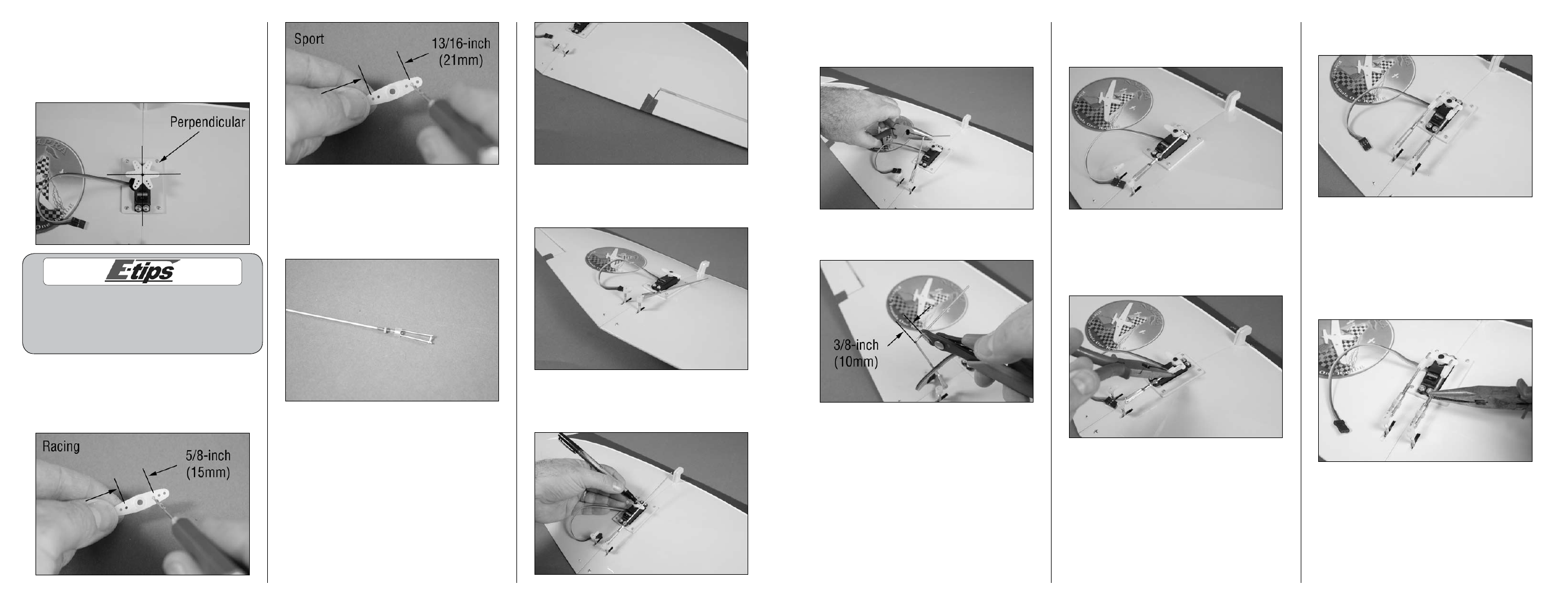
18. Use needle nose pliers to bend the pushrod
wire 90-degrees at the mark made in the previous
step.
19. Use side cutters to trim the wire 3/8-inch
(10mm) from the bend as shown.
20. Insert the linkage wire into the appropriate
hole in the servo horn for your particular flying
application.
21. Secure the linkage to the servo horn using a
nylon pushrod keeper. Slide the keeper on the bend
of the wire under the horn, then use pliers to snap
the rear portion of the keeper onto the linkage
wire.
22. Repeat Steps 14 through 21 to install the
remaining linkage.
23. Remove the low-tack tape from the ailerons.
Use the radio to check the operation of the
ailerons. Adjust the clevises if necessary so both
ailerons are centered when the servo is centered.
Use pliers to tighten the nut against the clevis to
prevent the clevis from changing positions in flight.
Slide the silicone keepers over the forks of the clevis
to keep them from accidentally opening in flight.
24. Disconnect the power and servo from the
receiver and turn the transmitter off at this time.
12. Use the radio system to center the aileron
servo. Install the servo horn so it is perpendicular to
the servo center line as shown. The servo horn has
an odd number of splines, so rotate it until the arms
are aligned, rather than using the sub-trim function
from the radio.
When installing the aileron linkage there are two
locations we suggest. One is for racing, making
the aircraft smoother and easier to control.
The other position is for general sport flying
which makes the aircraft more responsive.
13. Remove the servo horn from the servo. Use
side cutters to remove any unused arm from the
horn. Use a pin vise and 5/64-inch (2mm) drill
bit to enlarge the appropriate holes in the horn as
shown.
14. Slide a silicone keeper on the metal clevis.
Thread the nut on the 4
3
/
4
-inch (120mm) linkage
wire back so the metal clevis can be installed.
The threads on the linkage should just be visible
between the forks of the clevis.
15. Use a piece of low-tack tape to keep the
aileron centered when installing the linkage.
16. Use a flat blade screwdriver to open the forks
of the clevis enough to connect it to the aileron
control horn.
17. Use a felt-tipped pen to mark the linkage wire
where it crosses the appropriate hole in the servo
horn.