Propeller and spinner installation, Wing and stabilizer installation – E-flite LR-1A Pogo ARF 15e User Manual
Page 11
20
E-flite LR-1A Pogo 15e ARF Assembly Manual
21
E-flite LR-1A Pogo 15e ARF Assembly Manual
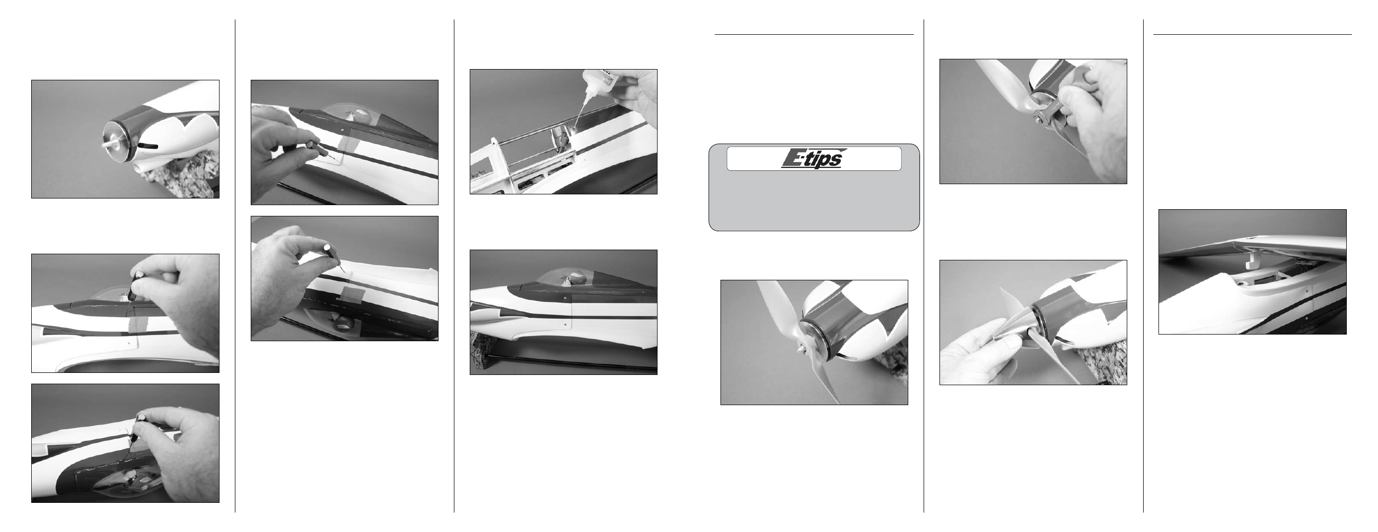
Propeller and Spinner Installation
Required Parts
Fuselage assembly
Propeller nut
Propeller washer
Propeller
Spinner cone with screw
Spinner backplate with adapter
Required tools and Adhesives
Hex wrench or ball driver: 3/32-inch
Open end or box wrench: 10mm
Always balance your propeller. An unbalanced
propeller can cause vibrations to be transmitted
into the airframe, which could damage the
airframe or other components as well as
produce unwanted flight characteristics.
1. Slide the spinner backplate and adapter on
the motor shaft. Then position the propeller on the
adapter as shown.
2. Install the propeller washer and nut on the
adapter. Use a 10mm box wrench or open end
wrench to tighten the propeller nut.
3. Position the spinner cone. Make sure the
opening in the spinner cone does not contact the
propeller. Use a 3/32-inch hex wrench or ball
driver to tighten the screw that secures the spinner
cone.
Wing and Stabilizer Installation
Required Parts
Wing assembly
Fuselage assembly
Wing bolt plate
4mm washer (2)
4mm x 30mm machine screw (2)
Required tools and Adhesives
30-minute epoxy
Phillips screwdriver: #2
Epoxy brush
Ruler
Felt-tipped pen
Mixing cups
Mixing sticks
Paper towels
T-pin
Low-tack tape
Rubbing alcohol
Hobby knife with #11 blade
1. Attach the wing to the fuselage by sliding the
tab on the wing under the plate inside the fuselage.
5. Check that the cowl is aligned with the spinner
backplate. There should also be a 5/64-inch
(2mm) gap between the backplate and cowl.
You may need to remove the tape and adjust the
position of the cowl for proper alignment.
6. Once aligned, use a pin vise and 1/16-inch
(1.5mm) drill bit to drill through the top two holes
in the cowl and into the fuselage.
7. Install two 2mm x 6mm sheet metal screws using
a #1 Phillips screwdriver to hold the position of the
cowl. Use a pin vise and 1/16-inch (1.5mm) drill
bit to drill the remaining two holes for mounting the
cowl.
8. Remove the cowl from the fuselage. Place
2–3 drops of thin CA in each hole to harden the
surrounding wood. This harder surface makes the
screws more secure when installed.
9. The cowl can now be secured to the fuselage
using the four 2mm x 6mm sheet metal screws.
Tighten the screws using a #1 Phillips screwdriver.