E-flite LR-1A Pogo ARF 15e User Manual
Page 15
28
E-flite LR-1A Pogo 15e ARF Assembly Manual
29
E-flite LR-1A Pogo 15e ARF Assembly Manual
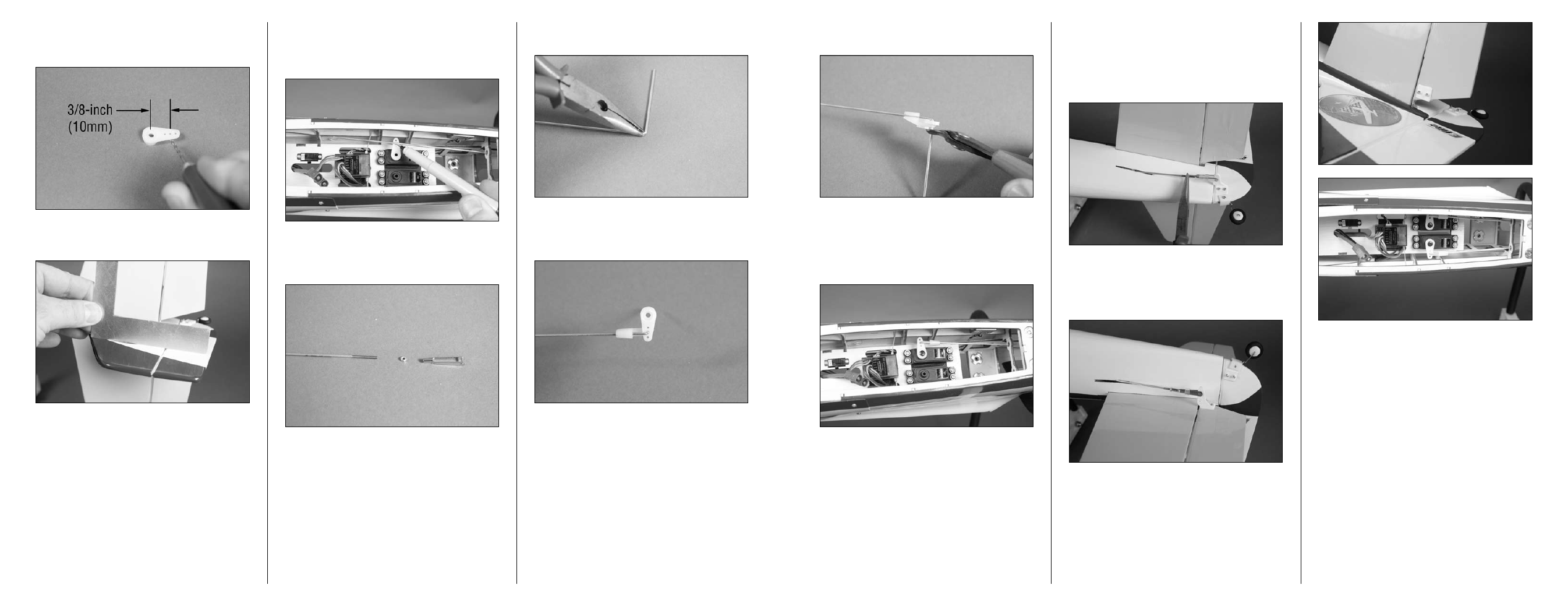
14. Use side cutters to trim the pushrod wire 1/16-
inch (1.5mm) from the pushrod keeper.
15. Slide the pushrod wire into the tube in
the fuselage. With the rudder servo centered,
secure the servo horn to the servo using the
screw provided with the servo and a #1 Phillips
screwdriver.
16. Thread the nut and clevis on the pushrod wire.
Connect the clevis to the rudder control horn and
check that the rudder is centered. If not, thread the
clevis in or out until the rudder is centered. Use
pliers to tighten the nut against the clevis to prevent
it from moving. Slide silicone keeper over the clevis.
17 Repeat Steps 1 through 16 to connect
the elevator pushrod wire. The positions and
measurements for the elevator connections are the
same as the rudder.
8. Use a pin vise and 5/64-inch (2mm) drill bit to
enlarge the hole in the servo arm that is 3/8-inch
(10mm) from the center of the servo horn.
9. Use a square of straight edge to make sure the
rudder is in alignment with the fin.
10. With the rudder and rudder servo centered,
place the servo horn on the servo. Use a felt-tipped
pen to mark the rudder pushrod where it crosses
the hole in the arm that was previously enlarged.
11. Remove the rudder pushrod from the fuselage.
Remove the nut and clevis from the pushrod wire.
Set the nut and clevis aside for now.
12. Use long nose pliers to bend the pushrod wire
90 degrees at the mark made in Step 10.
13. Slide the wire through the hole in the servo
horn. Use a nylon pushrod keeper to secure the
wire to the servo horn.