Electrical installation – Banner SI-HG63 Hinge Style Switches User Manual
Page 3
CAUTION:
End Stops.
Do not use the switch as an end stop. The operating angle of the switch must be limited by outer end
stops.
Setting the Switch Point
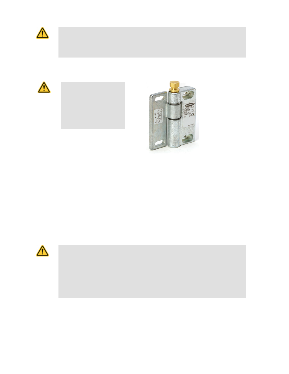
CAUTION:
Remove Set Screw Head.
Shear off the hexagonal head of
the set screw after it is set, and
before using the switch. If not, the
safe activation of the switch can
not be ensured.
Figure 1. Hinge switch with set screw head in place
1. Ensure the hinge switches (and blind hinges, if used) are properly mounted and the guard or gate swings freely throughout its range
of motion without binding. If binding is noticed, repeat the mechanical installation procedures.
2. Place the guard in its closed and latched position.
After the switch point is set, it cannot be changed. Before proceeding, verify the installation is correct and the resulting switching
action is what is expected.
3. Tighten the hexagonal set screw head with a 13 mm open-ended wrench (rotate clockwise when switch is mounted vertically and the
nut is on top). See
Figure 1. Hinge switch with set screw head in place
on page 3.
4. Continue tightening until the set screw head shears completely off the switch. When the screw head shears off, the switch point is
set.
Electrical Installation
CAUTION: Electrical Installation
Two safety switches must be used for each interlock guard to achieve control reliability or Safety
Category 4 (per ISO 13849-1, EN 954-1) of a machine stop circuit. Use of only one safety switch per
interlock guard is not recommended.
In addition, normally-closed safety contacts from each of the two safety switches should be connected to
the two separate inputs of a 2-channel safety module or safety interface. This is required to provide moni-
toring for safety switch contact failure, and to provide the necessary reset routine, as required by IEC
60204-1 and NFPA 79 machine safety standards.
Hinge Wing Safety Interlock Switches
P/N 046735 Rev. C
www.bannerengineering.com - tel: 763-544-3164
3