Scm strobe control module, Wiring – Banner PresencePLUS Interface Modules User Manual
Page 2
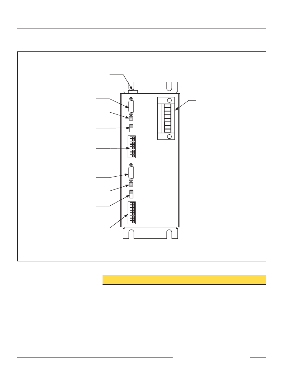
SCM Strobe Control Module
page
2
Banner Engineering Corp.
•
Minneapolis, U.S.A.
Website: http://www.baneng.com • Tel: 763.544.3164
Light 1
9-pin D-sub connector for
connection to LED light source
Rise/Fall 1
slide switch selection of low to high
("Rise") or high to low ("Fall")
trigger input signal
Test 1
Momentary push button
manual trigger
Output Channel #1
Pulse Width 1
8-segment DIP switches for binary
selection of output pulse duration
Light 2
9-pin D-sub connector for
connection to LED light source
Rise/Fall 2
slide switch selection of low to high
("Rise") or high to low ("Fall")
trigger input signal
Test 2
Momentary push button
manual trigger
Output Channel #2
Pulse Width 2
8-segment DIP switches for binary
selection of output pulse duration
Fuse
Removable terminal block
for connection of 24V dc module
power and trigger input signals
Wiring
Power Input
24V dc ±5% is connected between “+24V DC” and “DC GND” on
the removeable terminal block (see Figure 1). Power supply model
PSC-24(E) is recommended for powering the SCM, and is available
as an accessory (see page 4 and data sheet P/N 67466).
Trigger Inputs
The trigger signal must be a voltage between 5 and 12V dc. The
source of a trigger signal must be capable of supplying up to 10 mA.
2-wire shielded cable must be used. One 3 m (10') trigger cable is
supplied. Connect as indicated above, for each strobe channel used.
Figure 1. SCM Strobe Control Module feature identification