Installing the ring light, Wiring table – Banner PresencePLUS Lighting User Manual
Page 2
Stainless steel models: NEMA 4X; IP68
Operating Conditions
Temperature: 0° to +50° C (+32° to 122° F)
2. If necessary, use a lens cloth and lens cleaner or
window cleaner to wipe off remaining debris. Do not
use any other chemicals for cleaning.
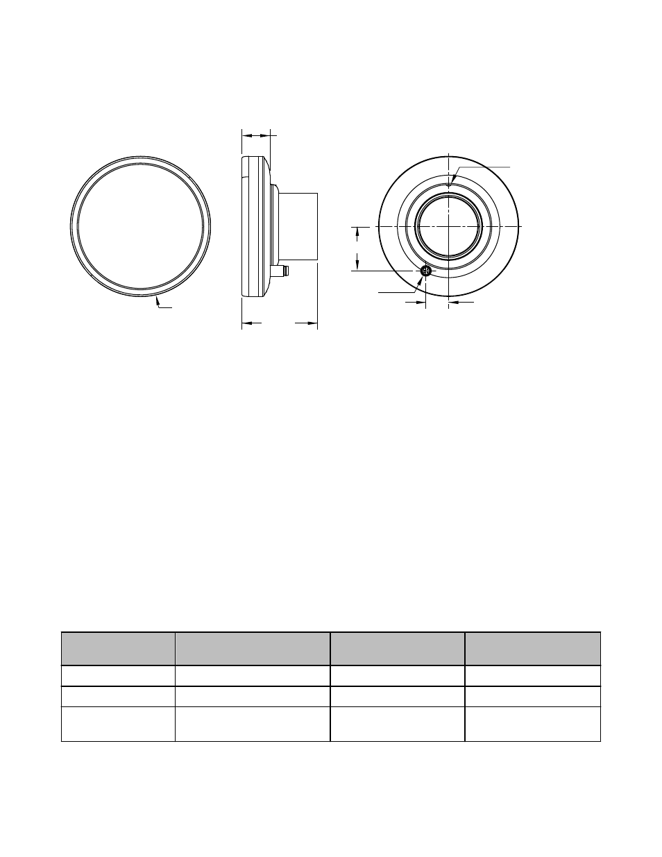
Ø 104.0 mm
(4.09")
22.3 mm
(0.88")
56.0 mm
(2.20")
33.0 mm (1.30")
16.8 mm
(0.66")
Cable Outlet
Set Screw
Figure 1. Dimensions
Installing the Ring Light
Before installing this ring light it is recommended that a light filter be installed behind the lens. The filter improves image quality by reduc-
ing unwanted ambient light. See Models table for further information.
1. Install and focus lens while holding ring light beside the sensor, illuminating the target.
2. Thread on ring light assembly until it is seated against the sensor.
3. Loosen the set screw and rotate the cable outlet to the desired position. Tighten set screw. Do not overtighten.
4. Install cable (not included, see page 3) to cable outlet.
5. Connect cable to power source.
6. Connect strobe signal output from Pro controller to strobe input wire (black) of light (optional).
Sensing Shiny Surfaces. To eliminate direct reflections without using polarizing filters, angle the sensor approximately 15° (or more)
from perpendicular to a shiny surface.
Polarizing Kit. If it is necessary to mount the sensor at a 90° angle to a shiny surface, the polarizing filter kit provides filters for both the
LED ring light and sensor to reduce the negative effects of strong, direct light reflections. The polarizing filters reduce the amount of light
returned to the sensor.
Wiring Table
Cable Wire
PresencePLUS Pro Controller Ter-
minal Block
External Power Supply (Stro-
bed)
External Power Supply (Con-
tinuous)
Brown
Pin 1 (+V*)
+V
+V
Blue
Pin 2 (-V*)
-V
-V
Black
Pin 4 (strobe)
+5V dc OFF
-V ON
-V
* For Banner-supplied wire
LEDxR90S Series Sealed Ring Lights
2
www.bannerengineering.com - tel: 763-544-3164
P/N 128842 rev. D