Modbus register table, Wiring diagrams for analog inputs, Wiring diagrams for analog outputs – Banner SureCross DX80 Wireless Networks User Manual
Page 5: Led behavior for the nodes
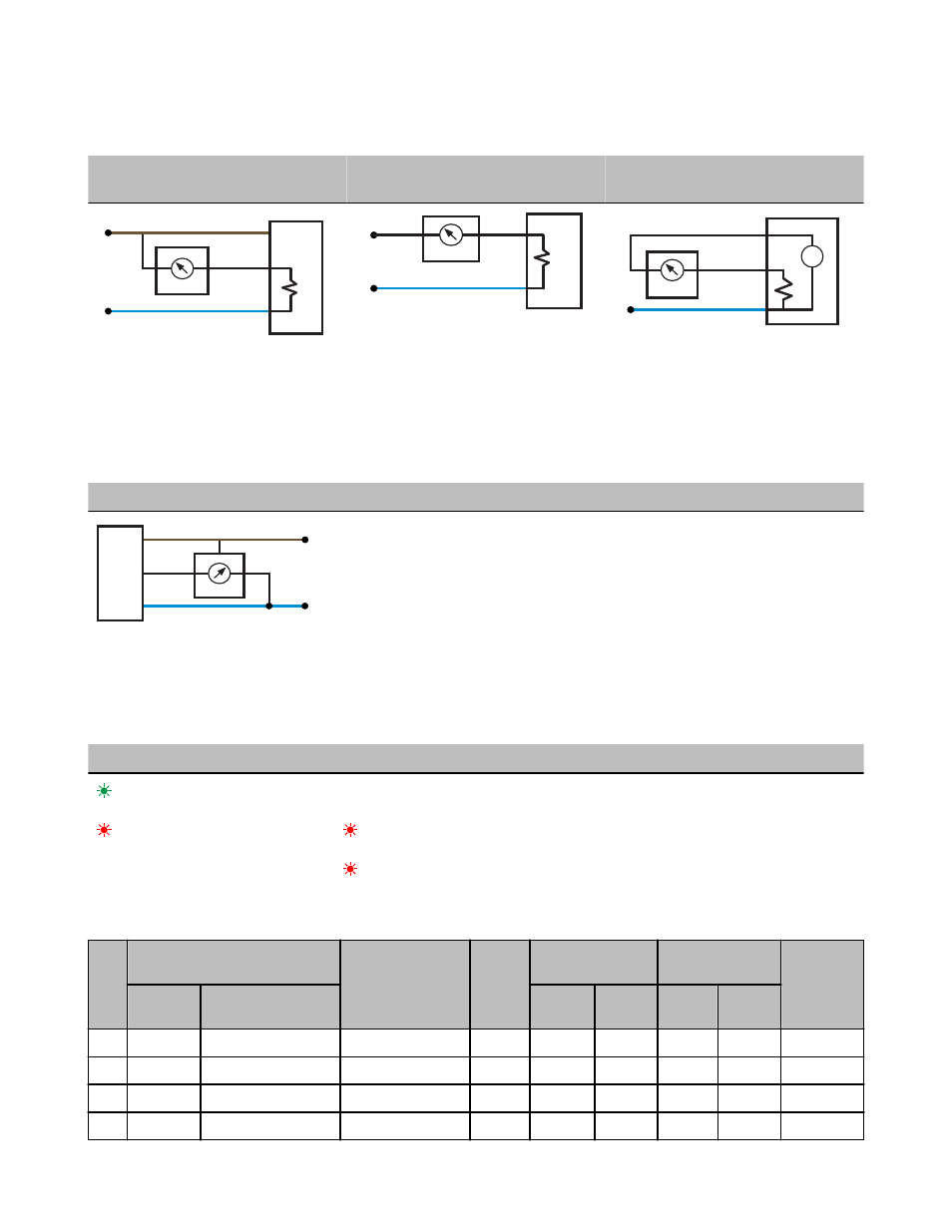
Wiring Diagrams for Analog Inputs
Connecting dc power to the communication pins will cause permanent damage. Do not exceed analog input ratings for analog inputs.
Only connect sensor outputs to analog inputs.
Analog Input Wiring (10 to 30V dc Pow-
er)
Analog Input Wiring (4–20mA, 2-Wire,
Externally Powered Sensors)
Analog Input Wiring (4–20mA, 2-Wire,
Switch Powered Sensors)
AIx
PWR
10-30V dc
GND
−
+
sensor
dc common
AIx
GND
dc common
external power
−
+
sensor
+
−
AIx
SPx
GND
−
+
sensor
dc common
(Only possible in models with switch power
(SPx) outputs)
Wiring Diagrams for Analog Outputs
Connecting dc power to the communication pins will cause permanent damage. Do not exceed analog input ratings for analog inputs.
Only connect sensor outputs to analog inputs.
Analog Output Wiring
AOx
GND
dc common
PWR
10-30V dc
sensor
LED Behavior for the Nodes
After powering up and binding the Gateway and its Nodes, verify all devices are communicating properly. A Node will not sample its
inputs until it is communicating with its Gateway. When testing communication between the Gateway and Node, all radios and antennas
should be at least two meters apart or the communications may fail.
LED 1
LED 2
Node Status
(flashing green)
Radio Link Ok
(flashing red)
(flashing red)
Device Error
(flashing red, 1 per 3 sec)
No Radio Link
Modbus Register Table
I/O
Modbus Holding Register
I/O Type
Units
I/O Range
Holding Register
Representation
Terminal
Block Labels
Gateway or
DX85
Any Node
Min. Val-
ue
Max. Val-
ue
Min.
(Dec.)
Max.
(Dec.)
1
1
1 + (Node# × 16)
Discrete IN 1
-
0
1
0
1
DI1
2
2
2 + (Node# × 16)
Discrete IN 2
-
0
1
0
1
DI2
3
3
3 + (Node# × 16)
Discrete IN 3
-
0
1
0
1
DI3
4
4
4 + (Node# × 16)
Discrete IN 4
-
0
1
0
1
DI4
SureCross DX80 Node
P/N 134323 Rev. G
www.bannerengineering.com - tel: 763-544-3164
5