Installation – Banner P4RE67-P PresencePLUS P4 Enclosures User Manual
Page 2
Banner Engineering Corp., 9714 Tenth Ave. No., Minneapolis, MN USA 55441 • Phone: 763.544.3164 • www.bannerengineering.com • Email: [email protected]
Model P4RE67-G / P4RE67-P Enclosure Kits
P/N 121996 rev. A
WARRANTY: Banner Engineering Corp.
warrants its products to be free from
defects for one year. Banner Engineering
Corp. will repair or replace, free of charge,
any product of its manufacture found to be
defective at the time it is returned to the
factory during the warranty period. This
warranty does not cover damage or liability
for the improper application of Banner
products. This warranty is in lieu of any
other warranty either expressed or implied.
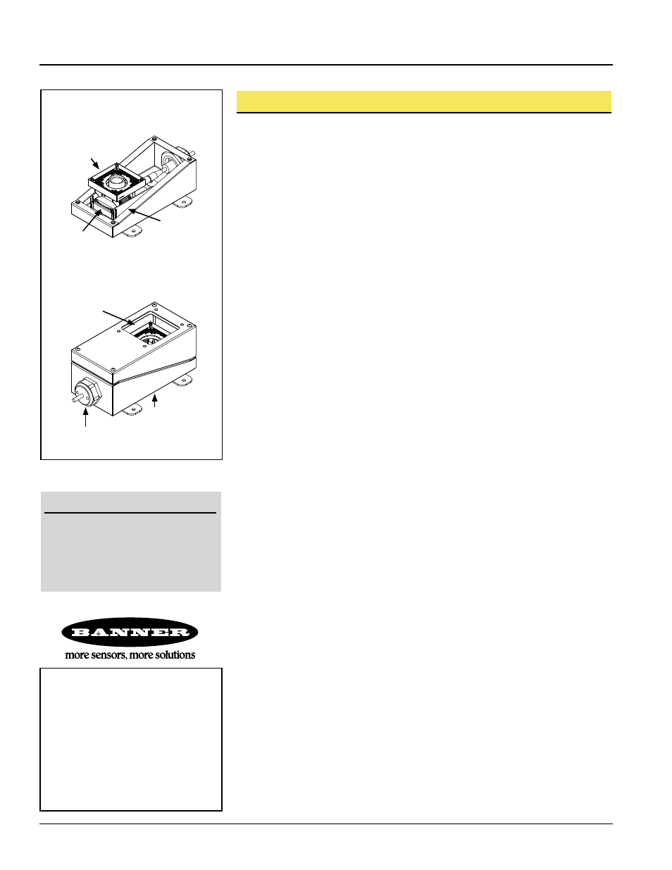
Figure 1. Assembling the Enclosure
Disassemble the Enclosure
1. Remove the four M5 slotted screws holding the housing halves together, and remove the
upper housing.
2. Remove the three nuts holding the bracket to the lower housing; remove the bracket.
Mount the Lower Housing
1. Drill four holes into the mounting surface. Use the base as a template, or see the dimension
drawing on page 1. (Mounting holes may be drilled or tapped.)
2. Mount the lower housing using four screws of sufficient size and length.
Mount the PresencePLUS
®
P4 Sensor
1. If not already done, mount the lens on the P4 sensor.
2. Mount the ring light (if used) on the sensor using two M3x6 socket-head screws, lock
washers and flat washers supplied with the ring light. Tighten both screws.
3. Mount the sensor on the bracket using the four M3x6 socket-head screws, lock washers,
and flat washers supplied with the sensor. Mount the sensor so the light housing or lens
(whichever protrudes more) is approximately 50 mm (2") above the top edge of the mounting
bracket.
4. Make sure that the sensor is perpendicular to the mounting surface and then tighten the four
screws securing the sensor to the mounting bracket.
5. Mount the sensor with bracket into the lower housing by aligning the three M5 studs with
holes in the bracket. Secure the bracket with three M5 lock nuts included with the enclosure
assembly.
Run Cable through the Cord Grip
1. Remove the crown nut and the two white insert halves from the cord grip assembly.
NOTE: The cord grip is shipped with the two small holes plugged for applications that do not
require the hookup of the Ethernet cable or NTSC video cable. If either of those cables
will not be used, keep the plug(s) so it can be reinstalled.
2. Run the sensor cable’s round connector-end through the crown nut and through the cord grip
body in the enclosure; snap it into the connector on the sensor bottom.
3. If used, run the Ethernet and NTSC cables into the enclosure as in step 2 and connect each to
its appropriate connector.
4. If using a ring light, connect the ring light cable to the connector on the sensor bottom.
NOTE: As drilled, the cord grip reduces the enclosure’s environmental rating to IP65. To achieve
IP67 (NEMA 6) specifications, apply RTV silicone sealant in the half-round cable grooves
of each white insert half before doing step 5.
5. Place one white insert half into the cord grip body, so the split is horizontal and the smallest
hole is on the left. Place all cables (or plugs) into their respective half-round grooves, and
slide the other white insert half into the cord grip body.
6. Making sure the cables are in place, thread the crown nut onto the cord grip body. Tighten it
securely by hand.
Power Up Sensor and Adjust the Camera Lens
1. Power up and verify that the sensor’s Power/Error light turns Green. Adjust lens focus and
aperture, then lock in place.
NOTES: If ring light is assembled for initial startup, you may need to remove ring light to lock
focus and aperture. A slight loss of illumination may occur when the enclosure is placed
over the camera.
Assemble the Enclosure
1. Using standard glass cleaner and a soft, non-abrasive cloth, clean the window on both sides
to prevent smudges that could cause imaging problems.
2. Align the enclosure gasket with the holes and edges on the lower housing; place the upper
housing over the sensor and onto the lower housing. Make sure the gasket holes are aligned
with the four enclosure holes and that the enclosure is pushed down fully.
3. Insert and evenly tighten the four M5 slotted screws securing the enclosure halves.
Ring Light
Enclosure Body
Cord Grip
Assembly
Window
Sensor and ring light
are not included.
Sensor
Bracket
Sensor
Tools Required:
• 8 mm deep-well socket on 100 mm
extension and ratchet (or 8 mm
open-end or box-end wrench)
• Standard flat-blade screwdriver
• 2.5 mm hex wrench (provided in sensor
and ring light hardware kits)
Installation
®