9 connection of the 813 compact autosampler, 1 electrical connection – Metrohm 757 VA Computrace User Manual
Page 47
3.9 Connection of the 813 Compact Autosampler
757 VA Computrace – Hardware
43
3.9
Connection of the 813 Compact Autosampler
With the 813 Compact Autosampler connected to the 757 VA Computrace Stand,
max. 18 samples can be transferred to the measuring vessel at the 757 VA Com-
putrace Stand. After each measurement, the measuring vessel is rinsed by means
of two 772 Pump Units connected to a 731 Relay Box. For operation of this sample
changer and the automatic addition of standard addition and auxiliary solutions by
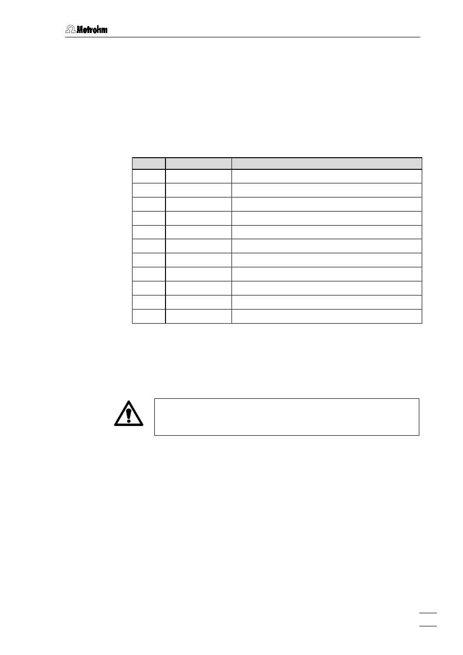
means of 765 Dosimats, the following instruments and accessory parts are needed
(see also section 6.2):
Quant.
Order no.
Instrument/Accessory
1
2.813.0020
813 Compact Autosampler for VA applications
1
2.731.0010
731 Relay Box
2
2.772.0010
772 Pump Unit
1 6.2141.150
Cable
813–757–731
1
6.5323.010
Rinsing equipment for VA
1…5 2.765.0010 765
Dosimat
1…5
6.3014.153
Exchange unit 5 mL (for addition solutions)
1…5
6.3014.213
Exchange unit 10 mL (for auxiliary solutions)
1 6.2141.080
Cable 757–2×765
or
1 6.9921.170
Cable 757–5×765
This section describes the procedure for the connection of 813 Compact Autosam-
pler, 731 Relay Box and 772 Pump Units. For the connection of 765 Dosimats, see
section 3.8.
3.9.1 Electrical
connection
Before any instruments are attached to the 757 VA Computrace Stand,
the 757 VA Computrace Stand must be
switched off using the mains
switch 12.
The 813 Compact Autosampler is connected to the socket "Remote" 15 of the 757
VA Computrace Stand with the optionally available
6.2141.150 Cable (see Fig. 15).
The second end of the 6.2141.150 cable is used to connect the 731 Relay Box. The
third end of the 6.2141.150 cable is used to connect 765 Dosimats with the
6.2141.080 cable (1...2 Dosimats) or the 6.9921.170 cable (1...5 Dosimats). At the
813 Compact Autosampler, "
Method 2" must be set (procedure see Instructions for
Use 813).
At the connection "DC1" of the 731 Relay Box, a 772 Pump Unit is connected as
si-
phoning pump, at the connection "DC2", a 772 Pump Unit is connected as rinsing
pump (see Instruction for Use 731 and 772). The output voltage of the 731 Relay
Box must be set to
+24 V (default setting, see section 2.3, Instruction for Use 713).
Additionally, the following settings for remote address selection must be done:
DC1: 9 (Siphoning pump)
DC2: A (Rinsing pump)