Dulce Systems PRO Mini User Manual
Page 43
PRO MINI Installation and User’s Manual
Page 43
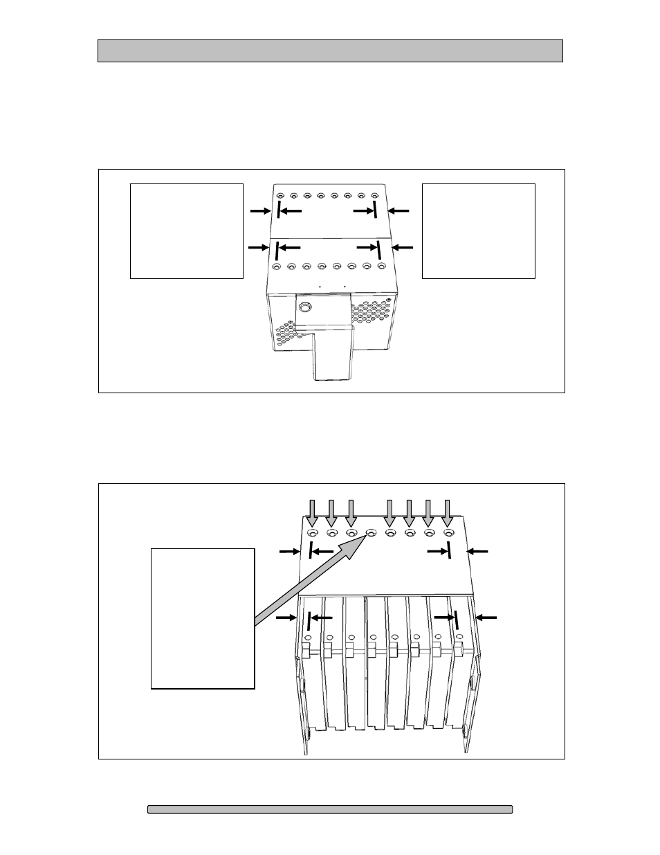
The 5
th
Step is to note the distance between the disk drive retaining screws and
the side of the MPD Pack. Disk Drive #1 (Slot #1) retaining screws are closer to
the side of the MPD Pack, and Disk Drive #8 (Slot #8) retaining screws are
further from the side of the MPD Pack. This notation will be helpful in the
following steps for replacing a disk drive, and for reassembling the MPD Pack.
6
th
Step – Locate the disk drive for replacement (#4 in this example) and remove
both retaining screws for the disk drive. Remove the disk drive from the MPD
Pack. Note: if the disk drive cannot be removed, or if the replacement disk drive
cannot be inserted, please also loosen the indicated disk drive retention screws.
Remove the two
disk drive screws
(top and bottom)
and remove the
faulty disk drive.
If necessary, also
loosen the seven
indicated disk
drive retention
screws.
Disk Drive #8 /
Slot #8
retaining screws
are further from
the side of the
MPD Pack
Disk Drive #1 /
Slot #1
retaining screws
are closer to
the side of the
MPD Pack