Autopilot system, gcu and gimbal wiring, Escription, Step1 – DJI H3-2D User Manual
Page 8: Ount the, Horizontally or vertically on the aircraft, Step2, Onnect, Utopilot, Ystem, Gcu port description
©2013 DJI Innovations. All Rights Reserved.
8
Autopilot System, GCU and Gimbal Wiring
GCU Port Description
Gimbal Controller Unit (GCU)
Port Description
3S~6S
To the battery. Power for the GCU and gimbal.
G8
To Gimbal, transmitting the signal.
Micro-USB port: PC connection for configuration and firmware upgrades.
CAN-Bus port: Use a CAN-Bus cable to connect the GCU to the autopilot system.
To Wireless Video Transmission Module, transmitting the Video signal.
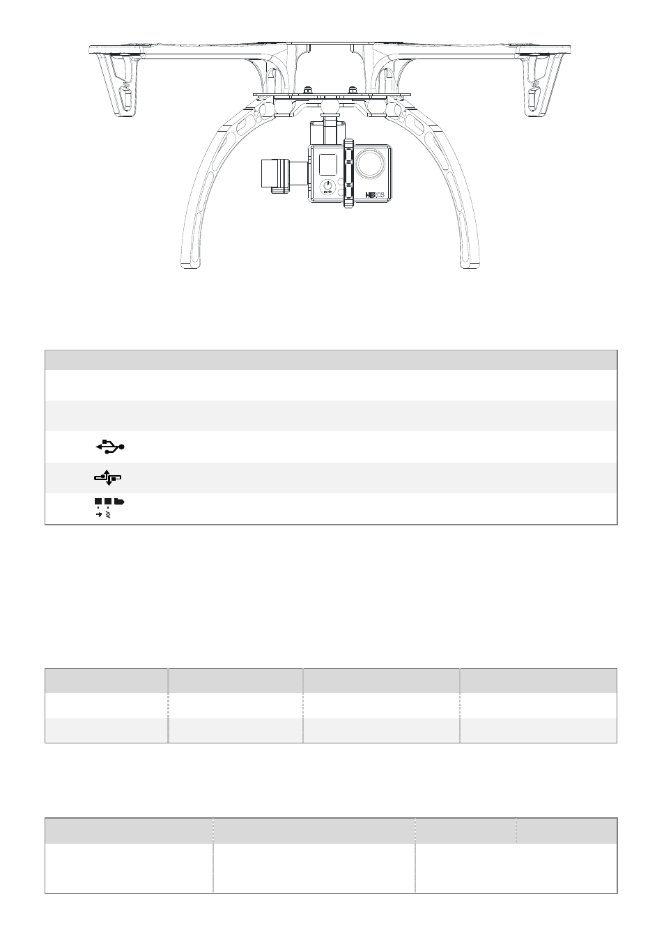
STEP1.
Mount the GCU horizontally or vertically on the aircraft.
STEP2.
Connect GCU and Autopilot System
Carry out the following procedures to finish the connection.
1.
Keep the Autopilot system in the same state as it was, and upgrade the Main Controller to the latest
Firmware (shown as the following table).
WKM
NAZA-M V2
NAZA-M
Assistant Software
V2.00
(or above)
V2.12(or above)
V2.12(or above)
Firmware Version
V5.22(or above)
V3.12(or above)
V3.12(or above)
2.
Connect the Autopilot System (shown as the following table). For NAZA-M user, you are asked to prepare a
PMU V2 module (Accessory of NAZA-M V2) and do some reconnection of the system.
WKM
NAZA-M V2
NAZA-M
(1) Main Controller and PMU
connection
Connect the X1 port of PMU to X1
port of Main Controller.
Connect the X3 port of PMU V2 to
X3 port of Main Controller.