Assembly, Imbal, Escription – DJI H3-2D User Manual
Page 5: Step1, Ount the, Imbal to the, Ircraft or, Anding, Gimbal description
©2013 DJI Innovations. All Rights Reserved.
5
Assembly
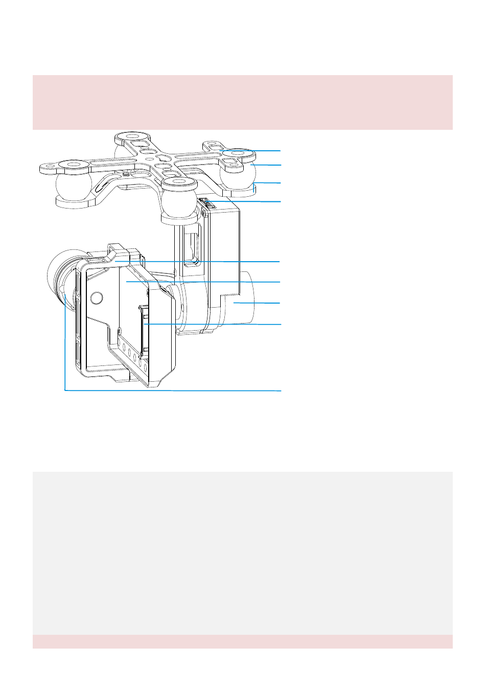
Gimbal Description
Notes:
(1)
Mack sure nothing blocks the servo driver module rotation, to avoid Servo Driver Module damage.
(2)
Clear obstacle at once if the rotating gimbal is blocked.
Top oard of the Damping Unit
B
Servo Driver Module(Roll)
Camera Fixed Mounting
Camera Interface
Servo Driver Module(Tilt)
Port of 8-Pin Cable
To GCU G8
(
)
Camera Mounting Base
Vibration Absorber
Bottom oard of the Damping Unit
B
STEP1. Mount the Gimbal to the Aircraft or Landing Gear
The following procedure applies to DJI F450, DJI other type of aircraft or to your own aircraft. For DJI F450,
there are diagrams for your reference.
1.
Attach the Vibration Absorber to the Top Board of Damper Unit shown in Fig.1.
2.
Mount the Top Board of Damper Unit to the Bottom Board of aircraft; fix the M3x8screws, M3 spacers
and M3 nuts shown in Fig.2.
3.
Plug one port of the 8-Pin cable into the 8-Pin port on the gimbal shown in Fig.3.
4.
Tighten the M2.5x5 screws to fix the gimbal to the Bottom Board of Damper Unit shown in the Fig.4 or
Fig5, select one of the steps according the position of screw threads.
5.
Attach the Vibration Absorber to the Bottom Board of Damper Unit shown in Fig.6.
6.
Make sure the damping unit is horizontally mounted and both damping boards are paralleled to the
bottom of the aircraft, further to make sure the gimbal is precisely and firmly assembled.
Notes: