Swivel flange cou pling .9, Unflanged cou pling .9, Swivel flange coupling – Bird Technologies 8578A100GIG User Manual
Page 19: Unflanged coupling
+
Note: The coupling must be fastened with all
four of the screws. Tighten evenly all around.
Swivel
Flange
Coupling
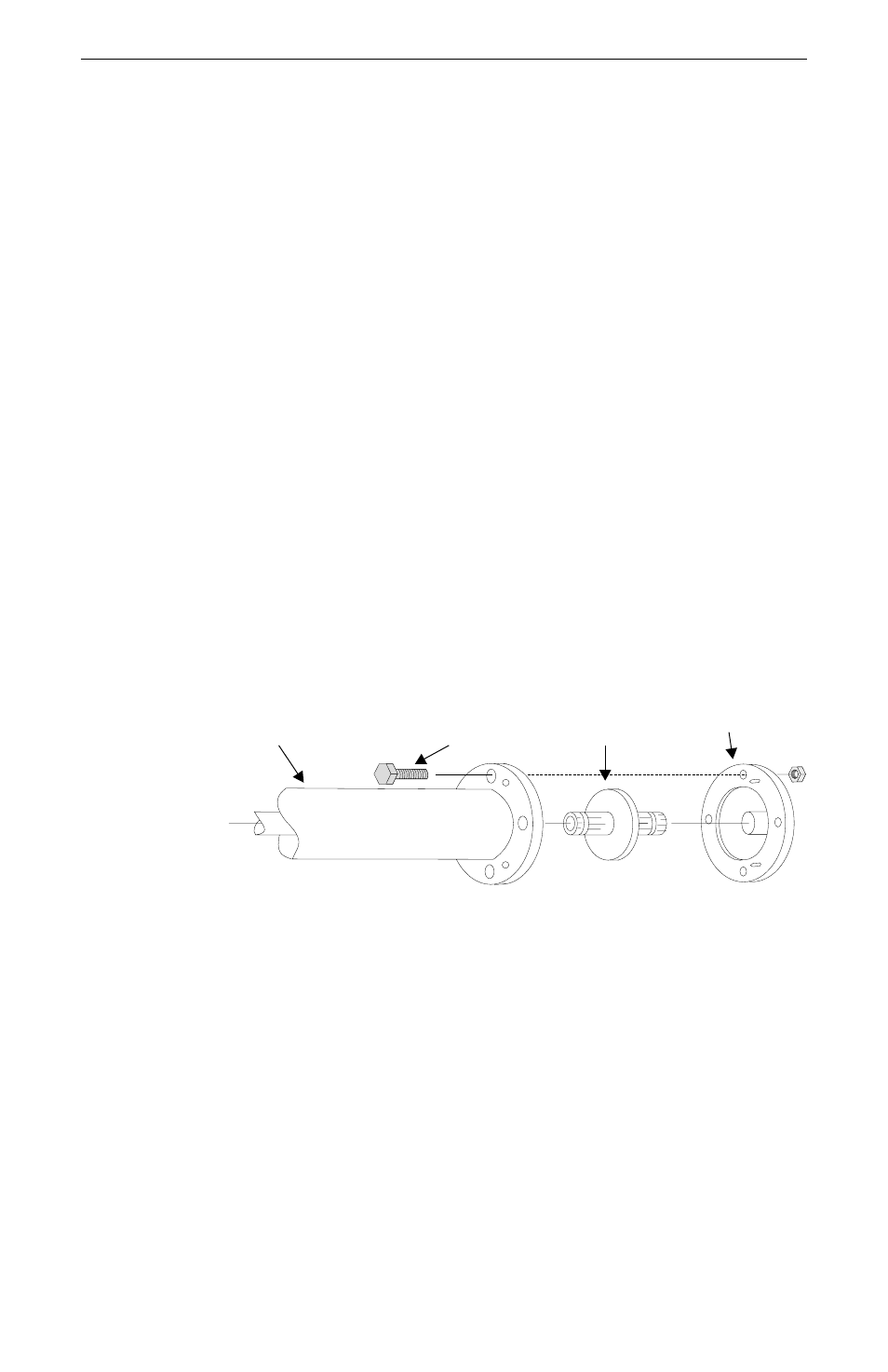
To couple the swivel flange with a flanged RF transmission
line, use 1-5/8 coupling kit P/N 4712-020. The kit includes:
four 5/16-18 x 1-1/2 bolt and nut sets, O-Ring, and insulated
center bullet. Refer to figure 4 while following the instruc-
tion below.
1. Insert the center bullet, push it in until it is
fully seated.
2. Install the O-Ring in the groove.
3. Connect the coaxial input in a straight line, push
carefully on the center conductor to close.
+
Note: The swivel flange on the load makes con-
nection independent of a fixed flange on the co-
axial input outer conductor.
4. Insert the bolt sets, tighten evenly all around.
Unflanged
Coupling
To couple the 3-1/8” unflanged connector with an unflanged
RF transmission line, use 3-1/8 inch unflanged coupling kit,
P/N 5-726. The kit includes: an outer sleeve with two clamp-
ing bands, and the center conductor coupling bullet. Refer to
figure 5 while following the instructions below.
1. Insert the center bullet and bottom it on the
midpoint nibs.
2. Position the outer sleeve, with clamps, over the
input connector.
Installation
9
RF Coaxial Line
Bolt
Bullet
Flange
Figure 4
Swivel
Flange
Coupling