Panel mount wiring, Figure 12 15v wiring schematic, Figure 13 12v wiring schematic – Bird Technologies ACM Series-Manual User Manual
Page 34
Bird Technologies
22
Panel Mount Wiring
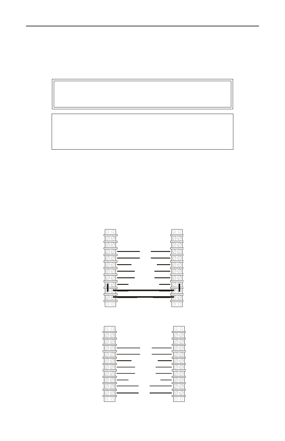
The power/alarm connectors for the Bird ACM Panel Mount are pro-
vided wired to the terminal strips. Figure 12, Figure 13, and Figure 14
show the wiring schematics for 15V, 12V, and 48V respectively.
Note the following, which apply to both panel styles:
z
The top two terminals are not used.
z
For either model, the power/alarm connector is wired identi-
cally on both terminal strips.
z
The 15V, 12V, and 48V connectors have different connection
callouts. Be sure to use the correct wiring schematic for each
specific model.
Figure 12 15V Wiring Schematic
Figure 13 12V Wiring Schematic
WARNING
Shock hazard. Remove AC power before attempting
to service the equipment.
CAUTION
The +15V supply should only be used to power the
ACM Panel.
Do not connect anything else to the power supply.
NO
NC
COMMON
ALARM
RESET
EARTH GND
EARTH GND
+15V
+
12V
–
NO
NC
COMMON
ALARM
RESET
EARTH GND
- SK-4000-TC-Manual (56 pages)
- SK-4000-TC-Datasheet (2 pages)
- SH-36S-Manual (206 pages)
- SH-36S-Datasheet (4 pages)
- SH-36S-PC-Manual (130 pages)
- SH-36S-PC-Datasheet (2 pages)
- SH-36S-PC-Quick Start (2 pages)
- SH-36S-RM-Datasheet (2 pages)
- SA-3600XT-Manual (112 pages)
- SA-3600XT-Datasheet (2 pages)
- AT-500-Manual (73 pages)
- AT-500-Datasheet (2 pages)
- AT-800-Manual (74 pages)
- 89-83F-02-03-Manual (2 pages)
- 89-83F-02-03-Datasheet (1 page)
- 8251 Series-Datasheet (1 page)
- 8251 Series-Manual (30 pages)
- DA10 VHF Series-Datasheet (2 pages)
- DA10 VHF Series-Manual (47 pages)
- 8865SC13-Datasheet (2 pages)
- 8865SC13-Manual (28 pages)
- 8890-300SC13-Manual (28 pages)
- 8921SC13-Manual (28 pages)
- 8931-115SC13-Manual (34 pages)
- BDS-Datasheet (2 pages)
- BDS-Manual (98 pages)
- SCC7 Series-Datasheet (2 pages)
- SCC7 Series-Manual (45 pages)
- MSCC7 Series-Datasheet (2 pages)
- MSCC7 Series-Manual (35 pages)
- SCC8 Series-Datasheet (2 pages)
- SCC8 Series-Manual (47 pages)
- 4020 Series-Datasheet (1 page)
- 4020 Series-Manual (4 pages)
- 4027A Series-Datasheet (2 pages)
- 4027A Series-Manual (6 pages)
- 4027F Series-Datasheet (2 pages)
- 4027F Series-Manual (6 pages)
- 4028 Series-Datasheet (2 pages)
- 4028 Series-Manual (6 pages)
- 7022-Datasheet (4 pages)
- 7022-Manual (27 pages)
- ACM Series-Datasheet (2 pages)
- BPME Series-Datasheet (4 pages)