Component description, Figure 1 antenna & cable monitor outline – Bird Technologies ACM Series-Manual User Manual
Page 15
Introduction
3
Component Description
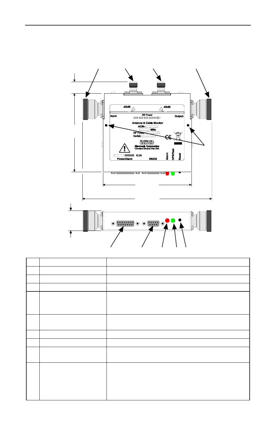
Figure 1 Antenna & Cable Monitor Outline
1
RF Input
Connect to the amplifier or combiner
2
Forward Monitor Port
Samples the forward travelling wave
3
Reflected Monitor Port Samples the reflected wave
4
RF Output
Connect to the antenna or feeder
5
Mounting Holes
Four holes, two top and two bottom, for positioning
the ACM on a rack. Supplied with 4-40 screws, will
fit M3 holes.
6
Reset Switch
Press to reset the alarm. If an alarm trigger is still
present, the alarm will reactivate
7
Operation/Test LED
Green LED that lights when the unit is powered
8
Alarm LED
Red LED that lights when an alarm is triggered
9
RS-232 Serial Port
9 pin female connector. Interface to a PC using a
male 9 pin RS-232 cable
10 Power/Alarm Parallel
Port
15 pin female connector (15 pin male connector on
models ACM-L2-DFDFTL-12SP and ACM-L2-
DFDFTH-48SP only). Connects to the power
supply using a male 15 pin cable. Also used for
remote operation.
1”
(27 mm)
6
7
8
9
10
4
3
2
1
5
0.8”
(20 mm)
4.2”
(107 mm)
7.0”
(178 mm)
4.75”
(121 mm)