Figure 5 db-15 power/alarm connector, male, Figure 6 power/alarm connector wiring, male – Bird Technologies ACM Series-Manual User Manual
Page 22
Bird Technologies
10
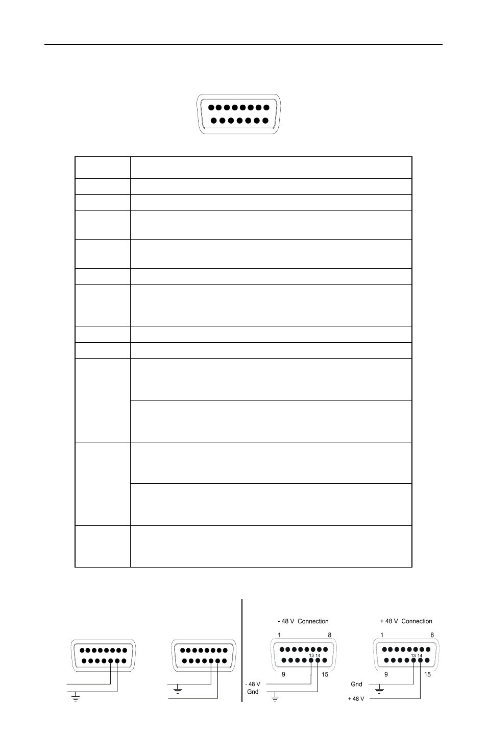
Figure 5 DB-15 Power/Alarm Connector, Male
Figure 6 Power/Alarm Connector Wiring, Male
Pin
Description
1-3
Internal connection
4
TTL compatible reset, 0 to +0.8 Vdc resets alarm
5
PTT input, +5V to +24V to activate,
0V or open to deactivate
6
TTL compatible alarm, 0 to
≥ 4.0 Vdc with a 10k load
when the alarm is active
7
Relay, common contact
8
Relay, normally closed contact (closed when relay is
not energized)
(open when there is no alarm)
9-10
DC input and signal ground
11-12
No connection (model ACM-L2-DFDFTL-12SP only)
13
DC input, 9 to 18 Vdc, - terminal
(model ACM-L2-DFDFTL-12SP only).
See DETAIL “A” in Fig. 6.
DC input, 36 to 72 Vdc, - terminal
(model ACM-L2-DFDFTL-48SP only).
See DETAIL “B” in Fig. 6.
14
DC input, 9 to 18 Vdc, + terminal
(model ACM-L2-DFDFTL-12SP only).
See DETAIL “A” in Fig. 6.
DC input, 36 to 72 Vdc, + terminal
(model ACM-L2-DFDFTL-48SP only).
See DETAIL “B” in Fig. 6.
15
Relay, normally open contact (open when relay is not
energized)
(closed when there is no alarm)
1
15
8
9
MALE (model ACM-L2-DFDFTL-12SP only)
- 12 V Connection
+ 12 V Connection
+ 12 V
- 12 V
Gnd
Gnd
13
13
14
14
1
15
8
9
1
15
8
9
DETAIL “A”
DETAIL “B”