Figure 3 db-15 power/alarm connector, female, Figure 4 power/alarm connector wiring, female – Bird Technologies ACM Series-Manual User Manual
Page 21
Installation
9
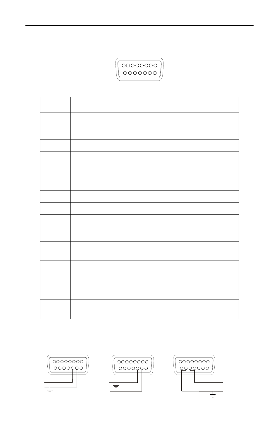
Figure 3 DB-15 Power/Alarm Connector, Female
Figure 4 Power/Alarm Connector Wiring, Female
Pin
Description
1
Relay, normally closed contact
(closed when relay is not energized)
(open when there is no alarm)
2
Relay, common contact
3
TTL compatible alarm, 0 to
≥ 4.0 Vdc with a 10k load
when the alarm is active
4
PTT input, +5V to +24V to activate,
0V or open to deactivate
5
TTL compatible reset, 0 to +0.8 Vdc resets alarm
6-8
Internal connection
9
Relay, normally open contact
(open when relay is not energized)
(closed when there is no alarm)
10
DC input, 36 to 72 Vdc, + terminal
(ACM-x-xxxxxH models only). See Fig. 4.
11
DC input, 36 to 72 Vdc, – terminal
(ACM-x-xxxxxH models only). See Fig. 4.
12-13
DC input, +11 to +26 Vdc (ACM-x-xxxxxL models only).
Pins 12 and 13 are internally connected (see Fig. 4).
14-15
DC input and signal ground. Pins 14 and 15 are internally
connected (see Fig. 4).
1
15
FEMALE
8
9
- 48 V Connection
+ 48 V Connection
- 11 V to + 26 V Connection
11
11
15
13
Gnd
Gnd
Gnd
- 48 V
+ 48 V
+ 11 V to + 26 V
10
10
14
12
1
15
8
9
1
15
8
9
1
8
9